
Heater with two different heat sources and air conditioner using the same

Active Publication Date: 2005-06-14
DENSO CORP
View PDF5 Cites 22 Cited by
  • Summary
  • Abstract
  • Description
  • Claims
  • Application Information

AI Technical Summary

Benefits of technology

[0005]In view of foregoing problems, it is an object of the present invention to provide a heater for heating air using two different heat sources, which effectively reduces pressure loss. It is another object of the present invention to provide an air conditioner using the heater, which reduces its size while reducing the pressure loss in an air passage.
[0009]When the heater is used for an air conditioner, the heater is disposed in a casing for defining an air passage through which air flows toward the room. In this case, when temperature of the fluid flowing out of a waste heat source unit is less than a predetermined temperature in a heating mode for heating air to be blown into the room, the high-pressure refrigerant is circulated in the refrigerant tubes. Because the heater has two heating functions using two different heating sources, the size of the air conditioner using the heater can be reduced. Further, even when the temperature of the fluid flowing out of the waste heat source unit is less than the predetermined temperature, air passing through the heater can be effectively heated by using the high-pressure refrigerant as the heating source.

Problems solved by technology

Thus, the mounting performance of the air conditioner is deteriorated, due to its large size.
However, because the sub-condenser and the heater are disposed serially in the air flow direction, pressure loss is increased while air passes through the sub-conditioner and the heater.

Method used


Image

  • Heater with two different heat sources and air conditioner using the same
  • Heater with two different heat sources and air conditioner using the same
  • Heater with two different heat sources and air conditioner using the same

Examples


first embodiment

[0020](First Embodiment)

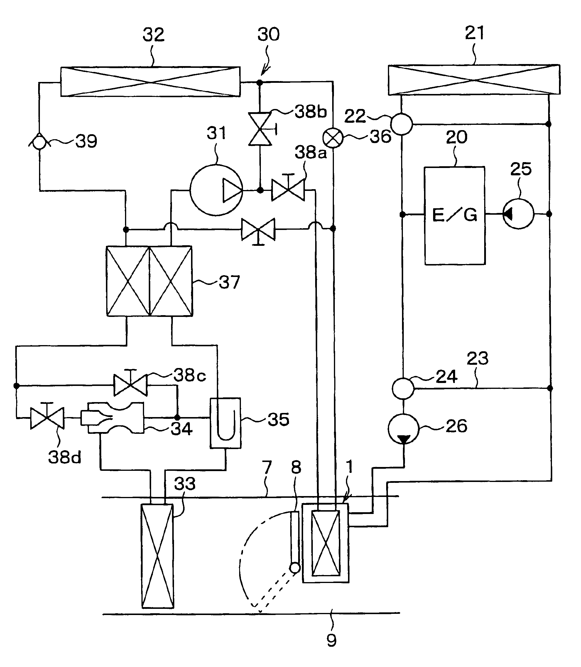
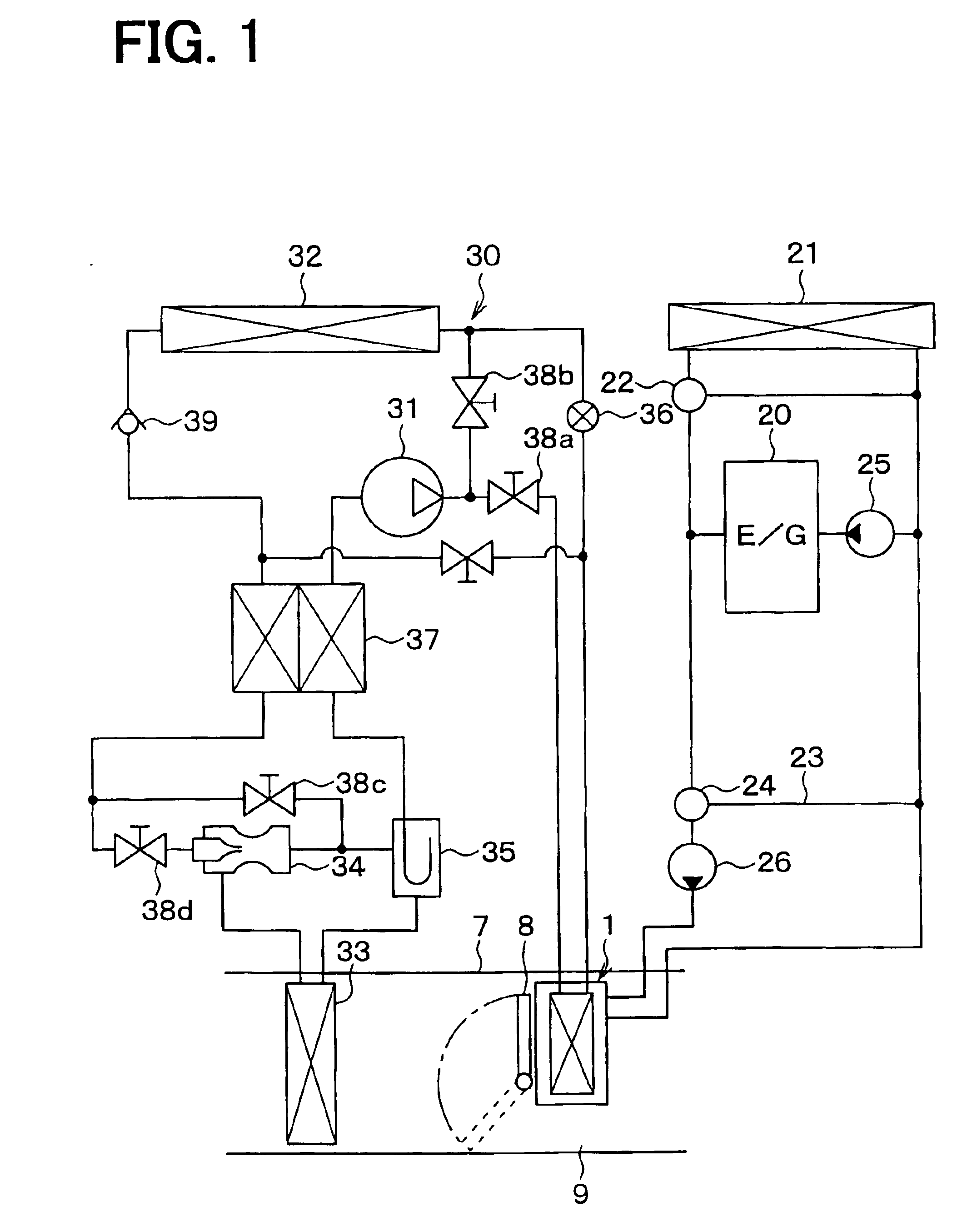
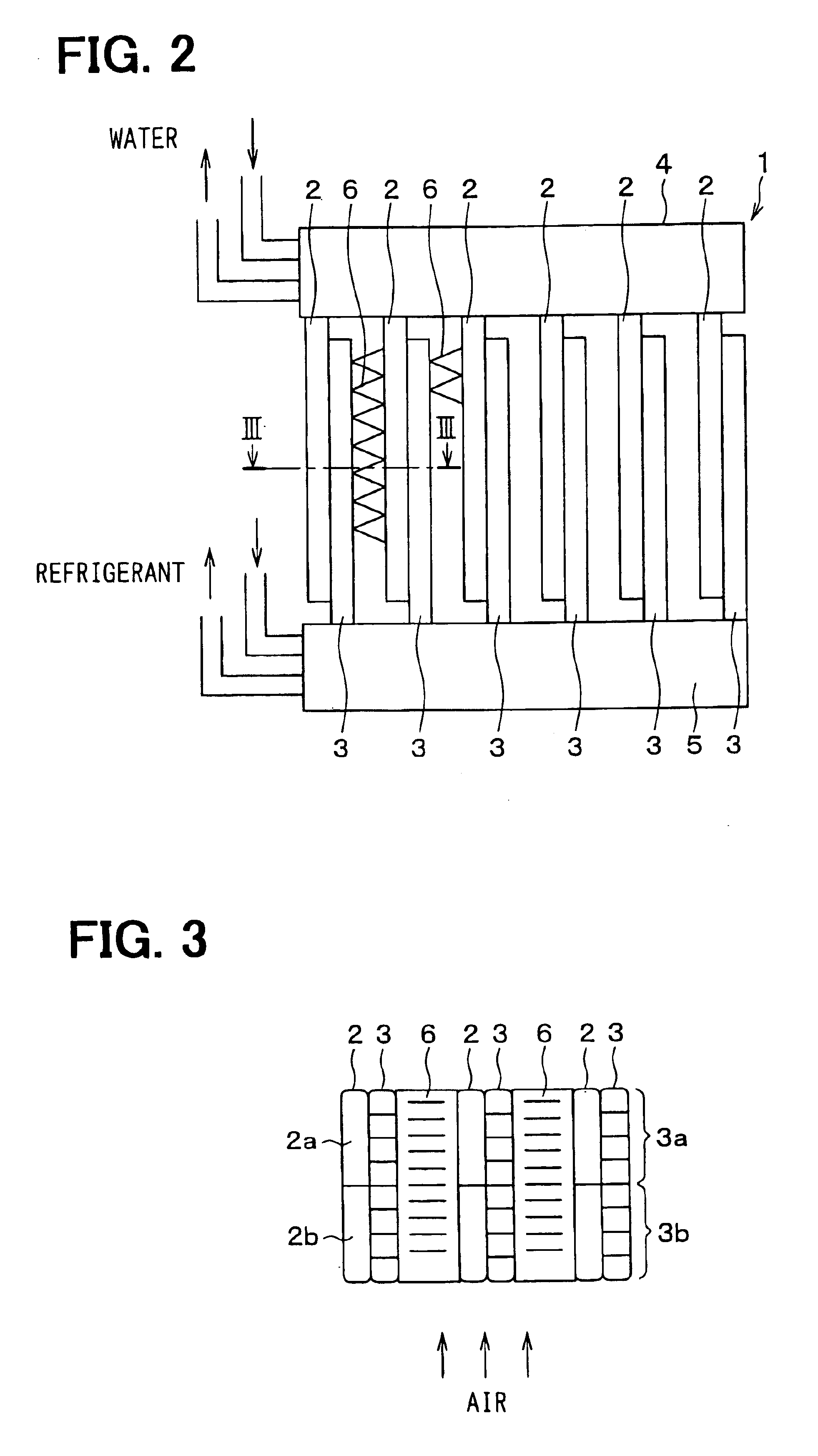
[0021]A heater 1 for heating air is disposed in an air conditioner as shown in FIG. 1. The heater 1 includes plural water tubes 2 and plural refrigerant tubes 3 as shown in FIG. 2 and FIG. 3. Engine-cooling water (hot water) flows in the water tubes 2 after circulating in an engine 20 (shown in FIG. 1) for recovering waste heat of the engine 20. High-pressure and high-temperature refrigerant is discharged from a compressor 31 of a vapor-compression refrigerant cycle 30 and flows into the refrigerant tubes 3. The vapor-compression refrigerant cycle 30 is a heat pump cycle for moving heat from a low temperature side to a high-pressure side. For example, the water tubes 2 and the refrigerant tubes 3 are alternatively arranged such that the longitudinal direction of the tubes 2, 3 are approximately parallel to each other.

[0022]As shown in FIG. 3, each water tube 2 is partitioned into plural passages extending in the tube longitudinal direction. In this embodiment...

second embodiment

[0053](Second Embodiment)

[0054]In the second embodiment, as shown in FIG. 9, the vapor-compression refrigerant cycle 30 has one of heating function and cooling function. That is, when the heater 1 has the heating function by using the high-temperature refrigerant discharged from the compressor 31, the interior heat exchanger 33 does not have the cooling function. On the other hand, when the interior heat exchanger 33 has the cooling function, the heater 1 does not have the heating function by using the high-temperature refrigerant. Besides, the bypass passage 23 and the switching valve 24 are reduced in the cooling water circuit of the engine 20. In the second embodiment, the other parts are similar to those of the above-described first embodiment.

[0055](Other Embodiment)

[0056]Although the present invention has been fully described in connection with the preferred embodiments thereof with reference to the accompanying drawings, it is to be noted that various changes and modification...


PUM


Abstract

A heater for an air conditioner includes plural water tubes and plural refrigerant tubes which are arranged in parallel in an air flow direction. Therefore, the heater can heat air by using at least one of the heating sources while a pressure loss in the heater can be effectively reduced. For example, in a quick-heating mode, high-temperature refrigerant from a refrigerant cycle flows into the heater to heat the blown air, and low-temperature engine-cooling water from an engine bypasses the heater. In this case, thermal leakage from the refrigerant to the engine-cooling water is avoided.

Description

CROSS REFERENCE TO RELATED APPLICATION[0001]This application is based on and incorporates herein by reference Japanese Patent Application No. 2002-270093 filed on Sep. 17, 2002, and No. 2003-276654 filed on Jul. 18, 2003.FIELD OF THE INVENTION[0002]The present invention relates to a heater with two heat sources and an air conditioner having the heater, which are effectively used for a vehicle.BACKGROUND OF THE INVENTION[0003]A vehicle air conditioner described in JP-A-9-263121 includes first and second heat exchangers and a heater, which are accommodated in one air-conditioning casing. The first heat exchanger and the second heat exchanger perform heat-exchange between refrigerant circulating in a vapor compression refrigerator and air to be blown toward a passenger compartment. On the other hand, the heater heats the blown air using engine-cooling water as a heat source. However, in this vehicle air conditioner, the two heat exchangers and the heater are accommodated in the heater ...

Claims


Application Information

Patent Timeline
IPC IPC(8): B60H1/04B60H1/00B60H1/08F25B13/00F25B27/00F28D1/04F25B9/00F25B40/00F25B30/06F25B30/00B60H1/03
CPCB60H1/00328B60H1/00885B60H1/00921B60H1/08F25B13/00F25B27/00F28D1/0426F28D1/0461B60H1/00342F28F2215/02B60H2001/00949B60H2001/00957B60H2001/3298F25B9/008F25B30/06F25B40/00F25B2309/061F25B2313/009F25B2313/02791F25B2327/00F25B2341/0012F25B2400/0407F28D2021/0096
Inventor ITO, KOJISHINDO, TOMOHIDEOKUMURA, YOSHIHIKOTOKUNAGA, TAKAHIROYAMAUCHI, YOSHIYUKI
Owner DENSO CORP
Learn More