
Method of making a glass preform for low water peak optical fiber

Inactive Publication Date: 2005-06-14
CORNING INC
View PDF43 Cites 49 Cited by
  • Summary
  • Abstract
  • Description
  • Claims
  • Application Information

AI Technical Summary

Benefits of technology

[0029]In one aspect, the present invention relates to a low water p

Problems solved by technology

However, as is well known, electromagnetic radiation traveling through an optical waveguide fiber is subject to attenuation or loss due to several mechanisms.
A particularly problematic component of optical fiber attenuation is the attenuation due to absorption by the optical waveguide fiber of impurities present in the light guiding region of the fiber.
Particularly troublesome is the attenuation caused by the hydroxyl radical (OH), which can be formed in the optical waveguide fiber when a source of hydrogen is present in the fiber material, or when hydrogen available from several sources during the fiber manufacturing process diffuses into the glass.

Method used


Image

  • Method of making a glass preform for low water peak optical fiber
  • Method of making a glass preform for low water peak optical fiber
  • Method of making a glass preform for low water peak optical fiber

Examples


example 1

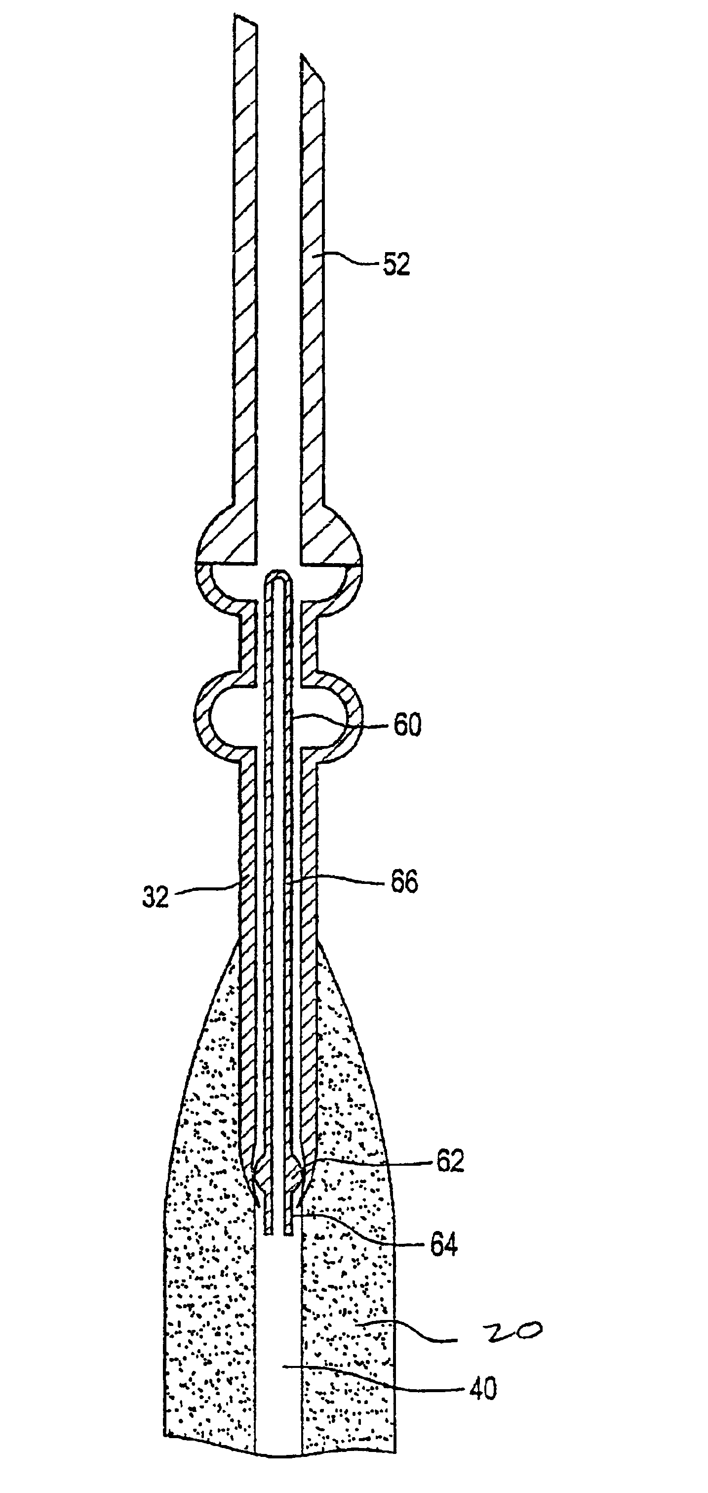
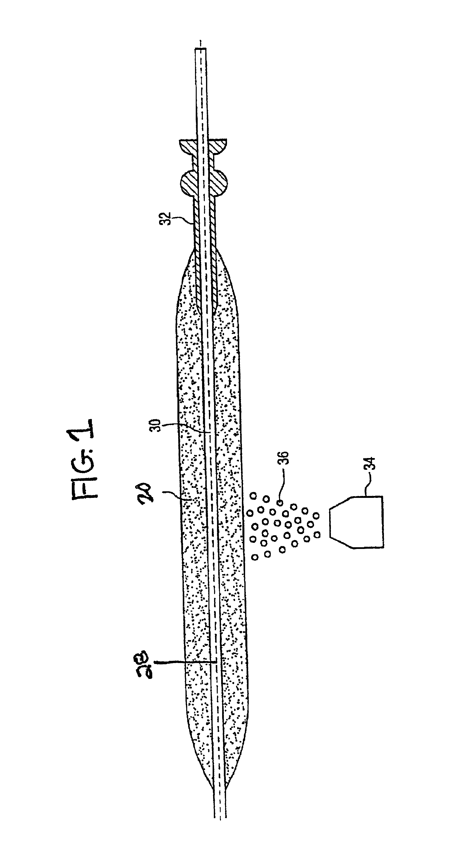
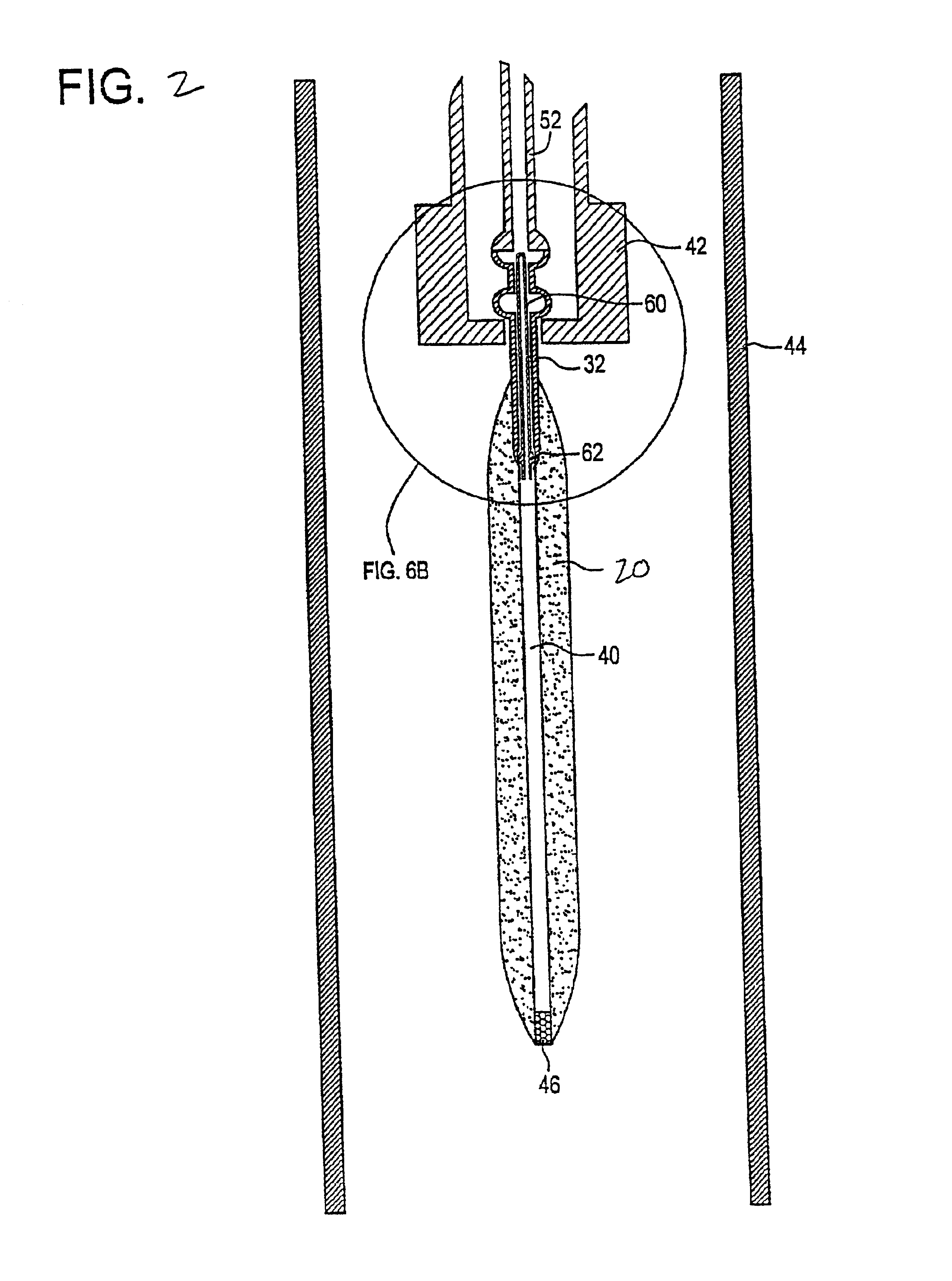
[0162]A membrane ballast plug or hollow tubular glass plug was exposed to about 3% D2 and balance nitrogen gas environment at a temperature of 1000° C. for about 24 hours. Germania doped soot was deposited onto a mandrel and a handle. The mandrel was removed, yielding a soot preform with a centerline hole with the handle jutting out one end. A tapered bottom tip plug was inserted into one end of soot preform opposite the handle with a friction fit. The previously deuterated membrane ballast plug was inserted into the other end of soot preform so that the membrane ballast plug rested in the handle at this point. The soot preform was dried with about 4% Cl2 (chlorine) and the balance helium gas at a temperature of 1125° C. for about 4 hours. The soot preform was then consolidated at a temperature of about 1500° C. in a helium gas environment. As the preform consolidated, the sintered glass pulled into engagement with the tip plug and the membrane ballast plug, thereby sealing the cent...


PUM

PropertyMeasurementUnit
Glass structureaaaaaaaaaa

Abstract

Optical waveguide fiber having low water peak as well as optical waveguide fiber preforms and methods of making optical waveguide fiber preforms from which low water peak and / or low hydrogen aged attenuation optical waveguide fibers are formed, including optical waveguide fiber and preforms made via OVD. The fibers may be hydrogen resistant, i.e. exhibit low hydrogen aged attenuation. A low water peak, hydrogen resistant optical waveguide fiber is disclosed which exhibits an optical attenuation at a wavelength of about 1383 nm which is less than or equal to an optical attenuation exhibited at a wavelength of about 1310 nm.

Description

RELATED APPLICATIONS[0001]This application claims the benefit of the priority date of U.S. Provisional Patent Application No. 60 / 258,179, filed on Dec. 22, 2000, entitled “Hydrogen Resistant Low Water Peak Optical Waveguide Fiber and Method of Manufacturing Same”, and U.S. Provisional Patent Application No. 60 / 272,015, filed Feb. 28, 2001, entitled “Low Water Peak Optical Waveguide Fiber”.BACKGROUND OF THE INVENTION[0002]1. Field of the Invention[0003]The present invention relates generally to the field of optical waveguide fibers, and more particularly to optical waveguide fibers having low water peak.[0004]2. Technical Background[0005]Generally speaking, a significant goal of the telecommunications industry is to transmit greater amounts of information, over longer distances, in shorter periods of time.[0006]Typically, as the number of systems users and frequency of system use increase, demand for system resources increases as well. One way of meeting this demand is by increasing ...

Claims


Application Information

Patent Timeline
IPC IPC(8): C03C13/04C03C25/60C03C13/00C03B37/014G02B6/02
CPCC03B37/01446C03B37/0146C03B37/01486G02B6/02C03C13/045C03C13/047C03C25/607C03C3/06C03B2201/075C03B2201/22C03B2201/31C03C2201/21C03C2201/22C03C2203/54
Inventor BERKEY, GEORGE E.BOOKBINDER, DANA C.FIACCO, RICHARD M.POWERS, DALE R.
Owner CORNING INC
Features
  • Generate Ideas
  • Intellectual Property
  • Life Sciences
  • Materials
  • Tech Scout
  • Unparalleled Data Quality
  • Higher Quality Content
  • 60% Fewer Hallucinations
Learn More