Disassemblable rolling mill stand

a technology of disassembly and rolling mill, which is applied in the direction of metal rolling stands, metal rolling stands, manufacturing tools, etc., can solve the problems of limiting reliability and complex assembling systems, and achieve the highest compactness and strength, the effect of simplifying the structure and ensuring the highest degree of stability

Inactive Publication Date: 2005-06-14
SIMAC
View PDF3 Cites 5 Cited by
  • Summary
  • Abstract
  • Description
  • Claims
  • Application Information

AI Technical Summary

Benefits of technology

[0010]it makes up vertical sliding jointed guide elements with corresponding opposite vertical counter-guides in said rolling mill assembly which couple inside of said opposite uprights with external retaining side extension, making up a joint, on the horizontal plane, with guide walls substantially shaped like two outwardly opened opposite “C”. Thus there is the advantage of simplifying the structure even allowing the total disassemblability and the highest compactedness and strength. In particular the guide system with opposite vertical guide uprights with inside-outside embedding, gives the highest solidity and safety in addition to a functionality which equals the integral structures, reducing at the minimum the slacks and dangers deriving from loosening.

Problems solved by technology

Because of their being disassemblable, the present rolling mill stands have a limited solidity or strength and anyway the fact of being disassemblable limits their reliability, also making the assembling system complex.

Method used


Image

  • Disassemblable rolling mill stand
  • Disassemblable rolling mill stand
  • Disassemblable rolling mill stand

Examples


Embodiment Construction

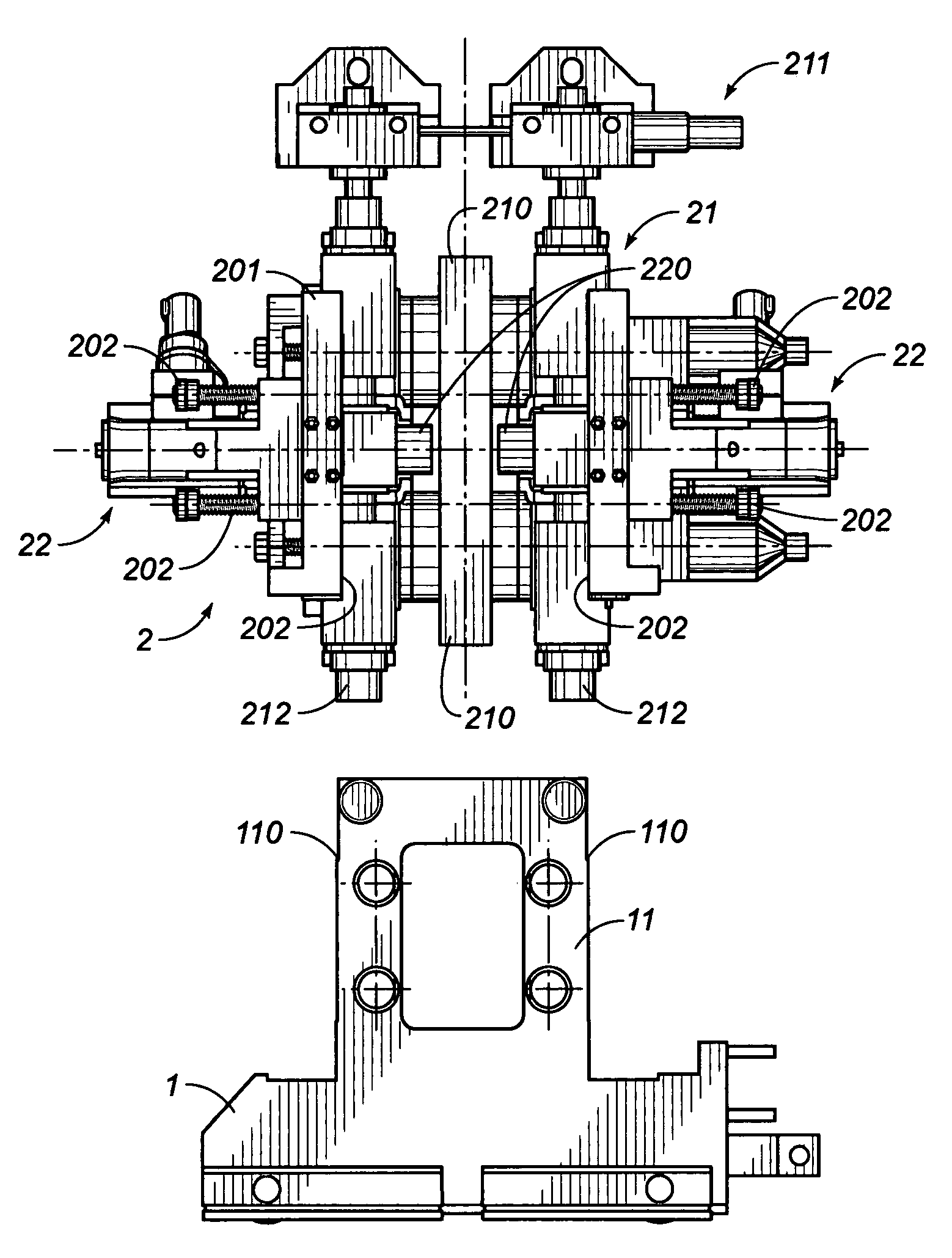
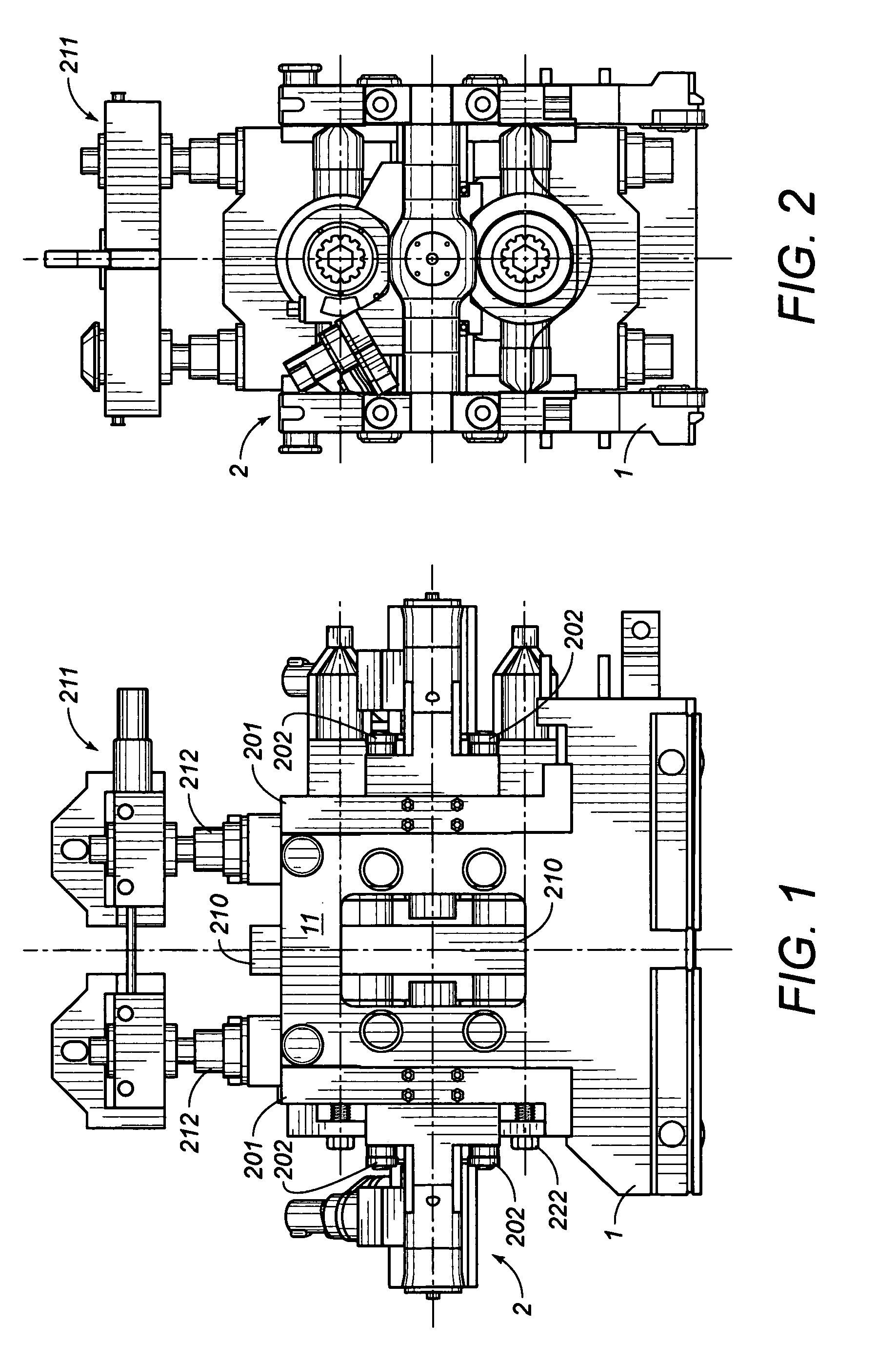
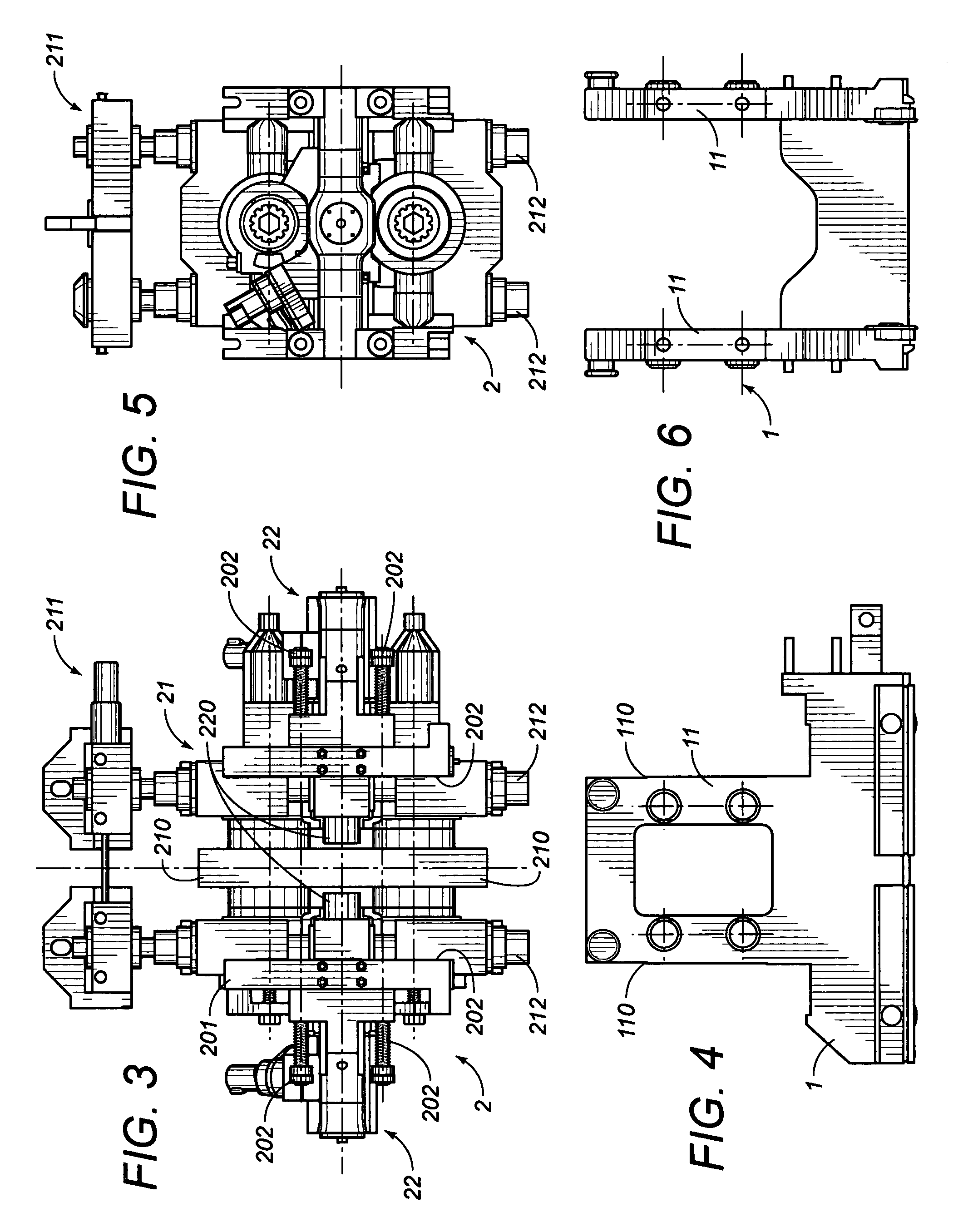
[0020]As it can be noticed in the above shown figures, the invention is substantially embodied in a disassemblable rolling mill stand, of the type involving a base structure (1) with a substantially “U”-shaped embedding structure (1), within whose uprights (11) the rolling mill assembly is embedded and fixed (2), with at least one couple of horizontal rolling cylinders (210–310), by screw fixing means (202-10 / 12).

[0021]The substantially “U”-shaped embedding structure:[0022]extends upwards with said guide uprights (11), advantageously up to the upper horizontal cylinder axis of said couple of horizontal rolling cylinders (210–310);[0023]it makes up vertical sliding jointed guide elements (11–110) with corresponding opposite vertical counter-guides (210) in the rolling mill assembly (2) with substantially opposite “C”-shaped embedding on the vertical plane, by jointing with side retention (201–110) of said guide uprights (11).

[0024]Said rolling mill assembly advantageously consists of...


PUM

PropertyMeasurementUnit
strengthaaaaaaaaaa

Abstract

Disassemblable rolling mill stand, of the type involving a bedplate structure with a substantially “U”-shaped embedding structure (1), within which the rolling mill assembly is embedded and fixed (2), with at least one couple of horizontal rolling cylinders (210–310), by fixing means (202-10 / 12), of said substantially “U”-shaped embedding structure, which extends upwards at least up to the upper horizontal cylinder axis of said couple of horizontal rolling cylinders (210–310) and makes up vertical sliding jointed guide elements (11–110) with corresponding opposite vertical counter-guides (201) in the rolling mill assembly (2).

Description

BACKGROUND OF THE INVENTION[0001]1. Field of the Invention[0002]The present invention are also relates to a disassemblable rolling mill stand.[0003]2. Description of the Related Art[0004]In prior art, disassemblable rolling mill stands are known. Solutions of disassemblable rolling mill stands are known, see for example IT-UD91A000118 (U.S. Pat. No. 5,457,979) and PCT / IT / 97 / 00237 (WO 98 / 15365) that uses two couples of screw-stays or screw tie-rods (1, 2, 3, 4), to join and tie the different components of a horizontal rolling stand, using a “U” shaped support basement realizing a cage (9) that extends upwards with uprights (90) till to enclose the lower part, including the lower horizontal cylinder (5, 1), of the whole horizontal rolling stand. U.S. Pat. No. 5,613,392 discloses a similar horizontal rolling stand with “U”-shaped basement whose uprights (2) extend upwards to encase (cage) the whole structure of the roller assemblies (both lower and upper cylinder). A “U” shape basement...

Claims


Application Information

Patent Timeline
Patent Type & Authority Patents(United States)
IPC IPC(8): B21B31/04B21B31/08B21B31/00B21B13/00B21B13/10B21B13/02
CPCB21B31/08B21B31/04B21B13/02B21B2013/106
Inventor NARDUZZI, LORENZO
Owner SIMAC
Why Eureka
Try Eureka