
Heat exchanger

a technology of heat exchanger and heat exchanger body, which is applied in the direction of indirect heat exchanger, light and heating apparatus, refrigeration components, etc., to achieve the effect of reducing internal pressure drop and facilitating assembly

Inactive Publication Date: 2005-06-14
VALEO INC
View PDF34 Cites 26 Cited by
  • Summary
  • Abstract
  • Description
  • Claims
  • Application Information

AI Technical Summary

Benefits of technology

[0006]In one preferred embodiment, the heat exchanger is a single pass exchanger. In such an embodiment, the first fluid is a refrigerant such that the first and second tubes are part of a condenser and the second fluid is an oil such that the one or more third tubes are part of an oil cooler. The third tubes comprise a return tube that normally has a cross sectionally fluid area larger than that of the smaller first and second tubes, to provide easier assembly and to reduce internal pressure drop. In another preferred embodiment, the one or more third tubes are above or below the one or more first and second tubes. In another preferred embodiment, the oil cooler includes an inlet supported by the first end tank and the inlet is below an outlet that is also supported by the first end tank. In still another preferred embodiment, the oil cooler is a single pass oil cooler with a lower tube, a higher tube and an inlet located nearer the lower tube than the higher tube. In yet another preferred embodiment, the heat exchanger includes a receiver having a bottom portion located below a lowest tube of the one or more second tubes.

Problems solved by technology

Such tubes generally have larger hydraulic diameters and cross sections than the second set of tubes, as they do not primarily perform heat transfer functions.

Method used


Image

  • Heat exchanger
  • Heat exchanger
  • Heat exchanger

Examples


Embodiment Construction

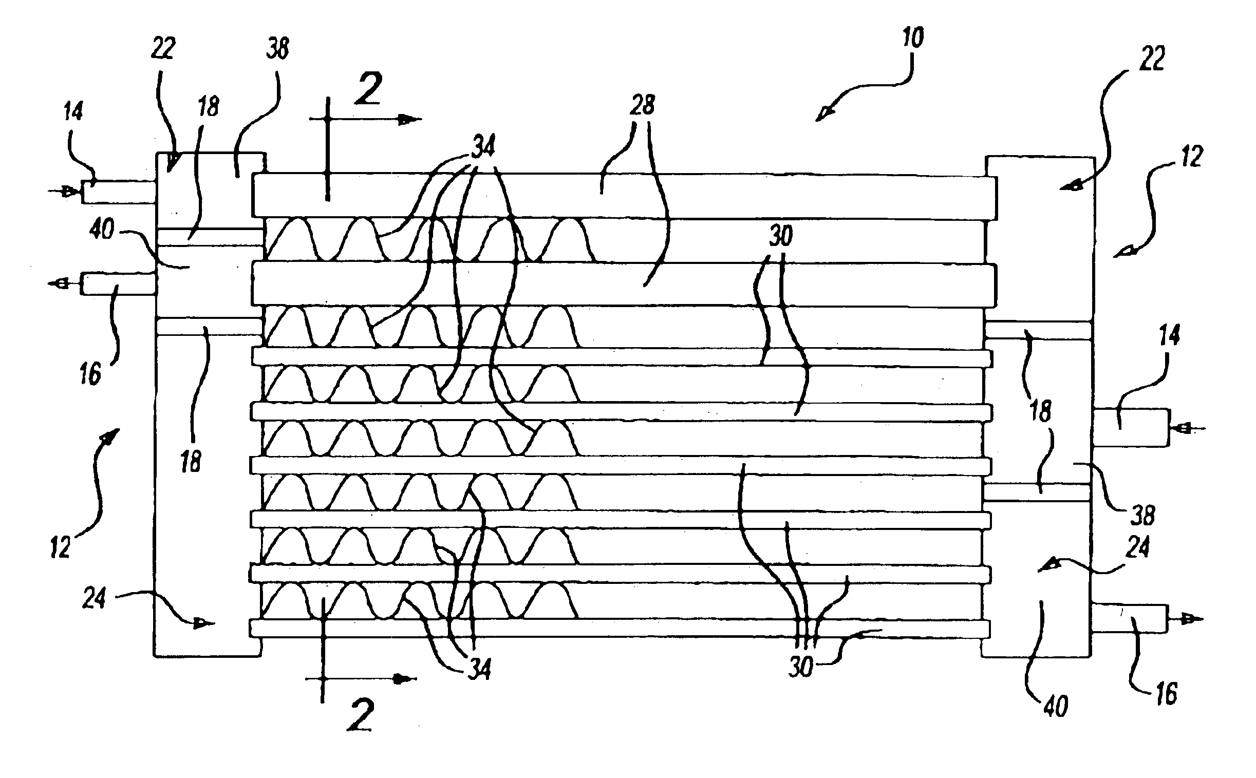
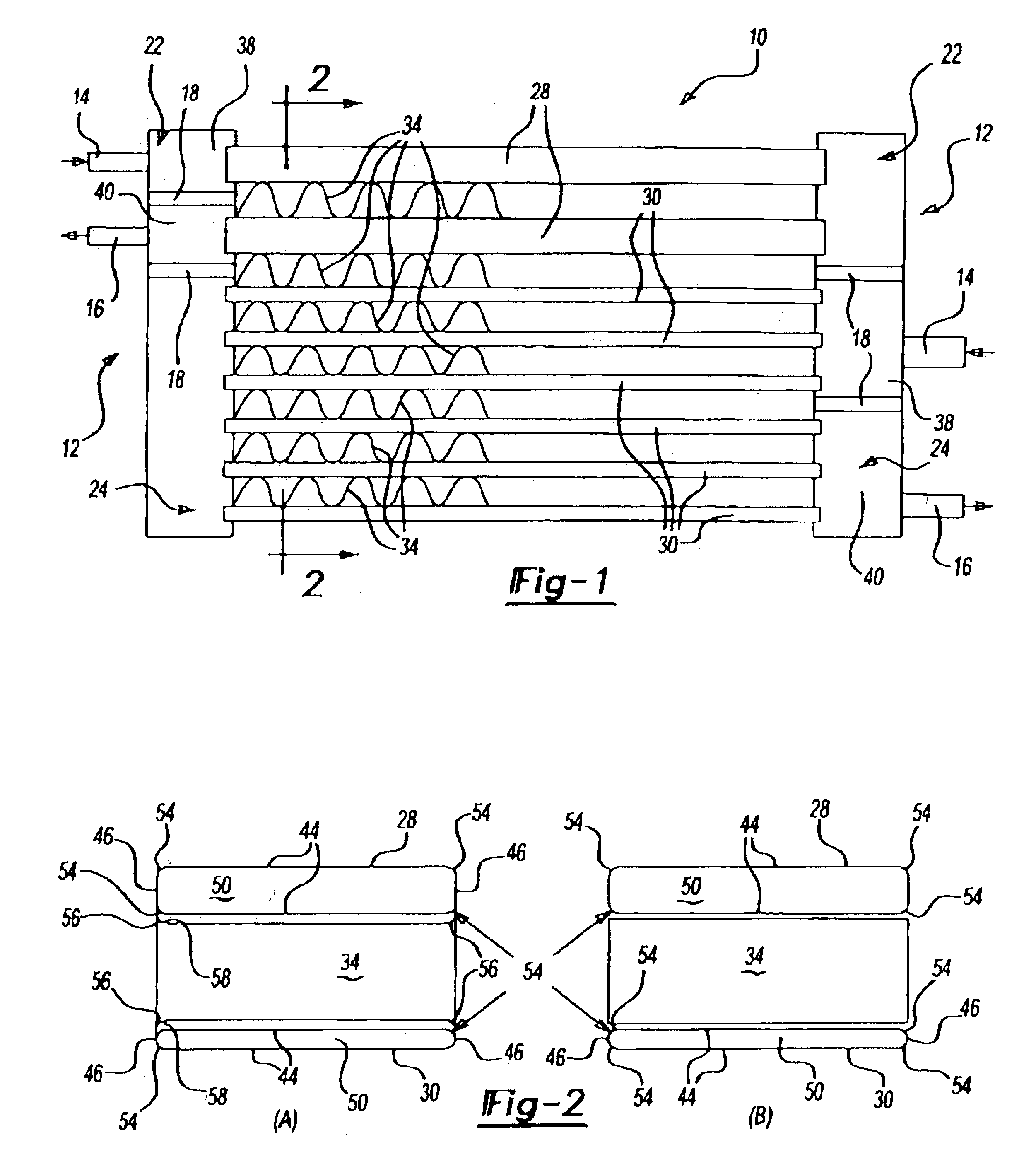
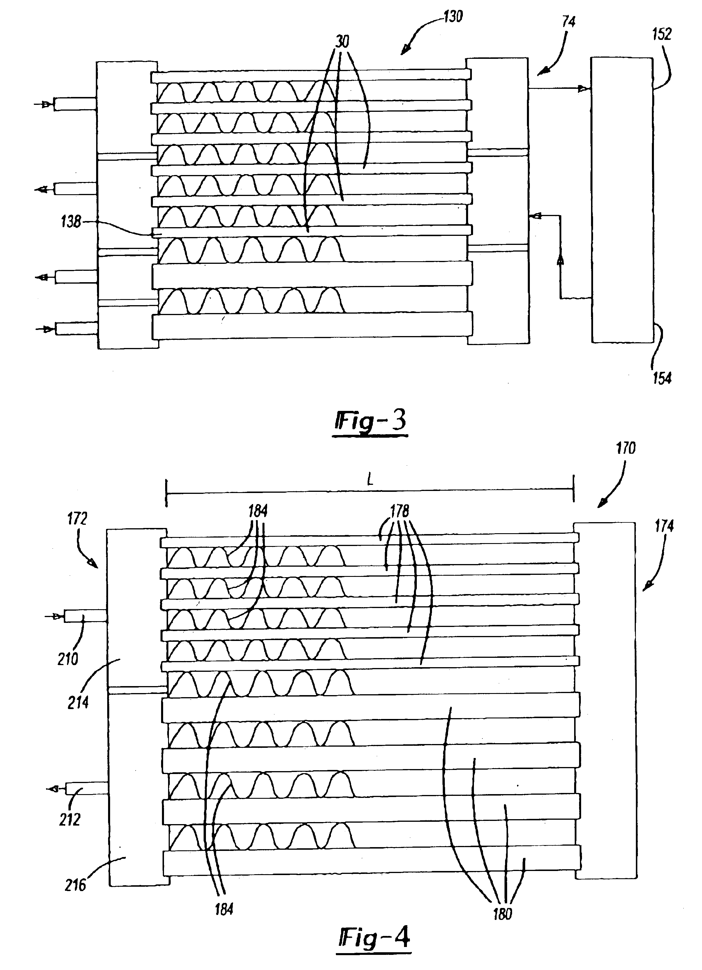
[0016]Generally, the present invention relates to a heat exchanger and to a method of forming the heat exchanger. The heat exchanger may be a single fluid or multi-fluid (e.g., 2, 3 or 4 fluid) heat exchanger. The heat exchanger may also be a single pass or multi-pass heat exchanger. Preferably, the heat exchanger in preferred embodiments of the present invention has fewer than three passes, more preferably the heat exchanger being a single pass or two pass heat exchanger. In preferred embodiments, where tube hydraulic diameter is less than or equal to about about 0.50 mm, the number of passes is preferably limited to one. In more preferred embodiments where in number of passes is limited to one, hydraulic diameter is most preferably less than about 0.40 mm. In a most preferred embodiment, where inlet and outlet are on the same side of the manifold / end tank, the heat exchanger is more preferably a two pass heat exchanger. Although the heat exchanger according to the present inventio...


PUM


Abstract

An improved heat exchanger, and, particularly, for an automotive vehicle, is disclosed. The heat exchanger typically includes at least one end tank; and a plurality of spaced apart metal tubes with fins between the spaced tubes. The heat exchanger may be single or multi-pass. In preferred embodiments, the heat exchanger is arranged to be single pass or two-pass and has tubes or tube arrangements to improve heat transfer efficiency.

Description

FIELD OF THE INVENTION[0001]The present invention relates generally to a heat exchanger and a method of forming the heat exchanger.BACKGROUND OF THE INVENTION[0002]It is generally desirable for heat exchangers to exhibit efficient transfer of heat. It is also generally desirable for fluids to flow through the heat exchangers without requiring unduly larger pressure drops for driving that flow. Additionally, and particularly in the automotive industry, it has become increasingly desirable to combine multiple functions in a single heat exchanger assembly. Additionally, multi-port tubes have been widely used in the automotive industry for high thermal efficiency and compactness reasons. Accordingly, the present invention seeks to provide an improved heat exchanger that exhibits one or more of these desirable characteristics. In heat exchangers, this desirability for fluids to flow through the heat exchangers without requiring unduly larger pressure drops for driving that flow, in addit...

Claims


Application Information

Patent Timeline
IPC IPC(8): F28F1/12F28F1/02F28D1/053F28D1/04
CPCF28D1/0443F28F1/022F28F1/126F28D1/05391F25B39/04F25B2339/0441F28F2009/0287
Inventor HU, ZAIQIAN
Owner VALEO INC
Features
  • Generate Ideas
  • Intellectual Property
  • Life Sciences
  • Materials
  • Tech Scout
  • Unparalleled Data Quality
  • Higher Quality Content
  • 60% Fewer Hallucinations
Learn More