Vehicular steering control device and vehicular steering control method

Active Publication Date: 2005-06-14
TOYOTA JIDOSHA KK
View PDF6 Cites 18 Cited by
  • Summary
  • Abstract
  • Description
  • Claims
  • Application Information

AI Technical Summary

Benefits of technology

[0009]It is an object of the invention to reliably prevent an excessive tensile stress from being applied to a spiral cable even if a steering wheel has been rotationally operated greatly by a driver i

Problems solved by technology

However, if the actuator is in a certain situation, the permissible rotational angle restricted by the spiral cable unit is insufficient.
As a result, an excessive ten

Method used


Image

  • Vehicular steering control device and vehicular steering control method
  • Vehicular steering control device and vehicular steering control method
  • Vehicular steering control device and vehicular steering control method

Examples


first embodiment

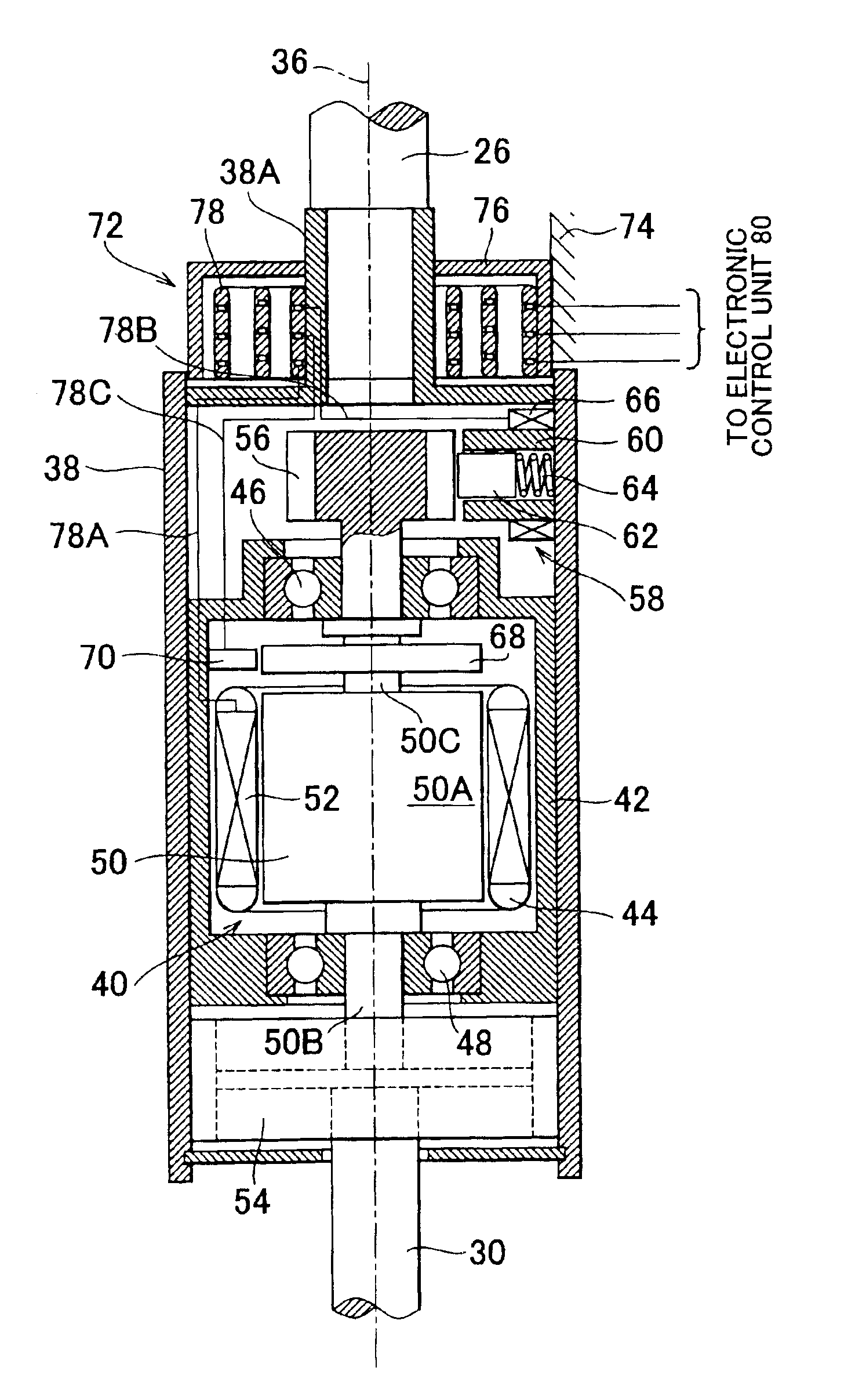
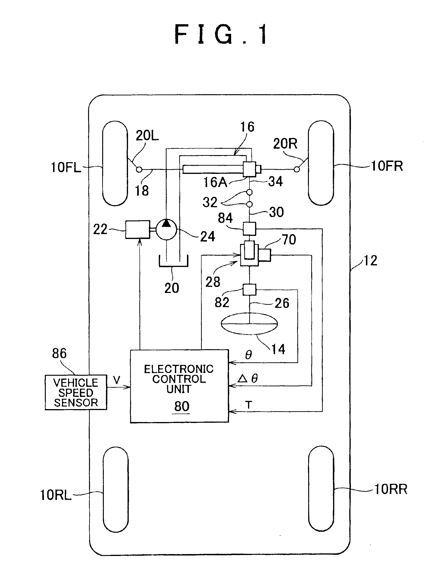
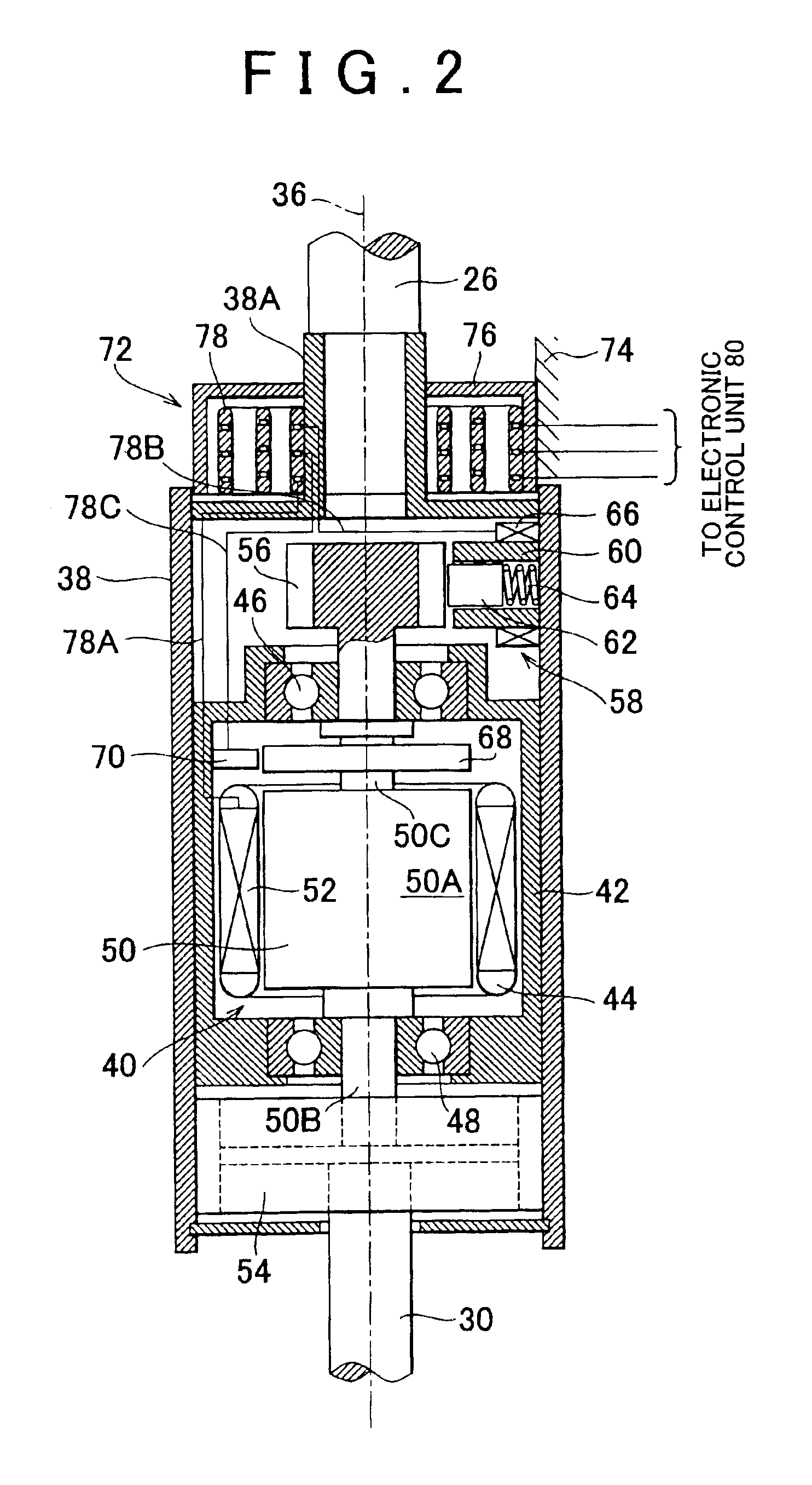
[0037]FIG. 1 is a block diagram showing an overall arrangement of a vehicular steering control device in accordance with the first embodiment of the invention which is applied to a vehicle provided with a hydraulic power steering unit. FIG. 2 is an enlarged cross-sectional view of a steering gear ratio change unit shown in FIG. 1.

[0038]Referring to FIG. 1, reference symbols 10FL and 10FR denote front-left and front-right wheels of a vehicle 12 respectively, while reference symbols 10RL and 10RR denote rear-left and rear-right wheels of the vehicle respectively. The front-left and front-right wheels 10FL and 10FR as steering wheels are turned by a hydraulic power steering unit 16 of rack-and-pinion type via a rack bar 18 and tie rods 20L and 20R. The hydraulic power steering unit 16 is driven in response to operation of a steering wheel 14 by a driver.

[0039]In the illustrated embodiment, the hydraulic power steering unit 16 has a control valve 16A having a known structure. High-press...

second embodiment

[0070]The aforementioned first embodiment is suited for cases where the electric motor can precisely control rotational angle, for example, as in the case of a stepper motor. However, the second embodiment and the third embodiment that will be described later are suited for cases where the electric motor is a motor constructed, for example, as a direct-current motor and where a rotational angle to be created by the electric motor is subjected to feedback control.

[0071]Next, a steering gear ratio control routine in accordance with the second embodiment will be described with reference to a flowchart shown in FIG. 8. In FIGS. 8 and 3, like steps are denoted by like step numbers.

[0072]In the second embodiment, step 11 follows step 10. It is determined in step 11 whether or not a relative rotational angle Δθ which is formed between the upper steering shaft 26 and the lower steering shaft 30 and which has been detected by the rotational angle sensor 70 has exceeded a reference value Δθta...

third embodiment

[0078]FIG. 9 is a flowchart showing a steering gear ratio control routine in accordance with the third embodiment. In FIGS. 9 and 3, like steps are denoted by like step numbers.

[0079]In the third embodiment, step 21 follows step 20. It is determined in step 21 whether or not a target relative rotational angle Δθt which is formed between the upper steering shaft 26 and the lower steering shaft 30 and which has been calculated in step 20 has exceeded a reference value Δθtrs (a positive constant that is smaller than and close to Δθtarmax) in the right-turn direction. If an affirmative determination is made, the control operation proceeds to step 26. If a negative determination is made, the control operation proceeds to step 22.

[0080]It is determined in step 22 whether or not a target relative rotational angle Δθt which is formed between the upper steering shaft 26 and the lower steering shaft 30 and which has been calculated in step 20 is below a reference value Δθtls (a negative const...


PUM


Abstract

A target relative rotational angle Δθt which is created by a steering gear ratio change unit and which is formed by a lower steering shaft relative to an upper steering shaft is calculated on the basis of a steering angle θ, and a post-correction target relative rotational angle Δθta to be created by the steering gear ratio change unit is calculated on the basis of the target relative rotational angle Δθt and a vehicle speed range that has been determined on the basis of a vehicle speed V. Thus, a target relative rotational angle in one lateral direction is so corrected as to be equal to or smaller than a difference between a permissible rotational angle to be defined by a spiral cable in the other lateral direction and a maximum possible rotational angle of the lower steering shaft in the other lateral direction. An electric motor is controlled on the basis of the post-correction target relative rotational angle Δθta.

Description

INCORPORATION BY REFERENCE[0001]The disclosure of Japanese Patent Application No. 2002-218261 filed on Jul. 26, 2002, including the specification, drawings, and abstract is incorporated herein by reference in its entirety.BACKGROUND OF THE INVENTION[0002]1. Field of the Invention[0003]The invention relates to a vehicular steering control device and a vehicular steering control method, more particularly, to a steering control device having steering transmission ratio change means and a method for the steering control device.[0004]2. Description of the Related Art[0005]As one vehicular steering control device for an automobile or the like having steering transmission ratio change means, for example, there has been known a steering control device disclosed in the U.S. Pat. No. 6,164,150, which was also filed by the present applicant. This steering control device has an input portion coupled to a steering wheel operated by a driver, an output portion drivingly connected to steered wheel...

Claims


Application Information

Patent Timeline
IPC IPC(8): B62D5/04B62D6/00B62D5/00B62D5/07B62D113/00B62D119/00B62D137/00
CPCB62D6/002B62D5/008
Inventor KOJO, TAKAHIROKAWAMURO, JUNJINAKATSU, MASATOSHI
Owner TOYOTA JIDOSHA KK
Why Eureka
Try Eureka