
Convertible

a convertible and side frame technology, applied in the direction of windows, windscreens, superstructures, etc., can solve the problems of complicated folding mechanism of the side frame parts shown, additional steps must be taken, etc., to avoid increased tensile stress on the covering, improve folding, and optimize the effect of the covering

Inactive Publication Date: 2008-09-30
WILHELM KARMANN GMBH
View PDF15 Cites 2 Cited by
  • Summary
  • Abstract
  • Description
  • Claims
  • Application Information

AI Technical Summary

Benefits of technology

[0006]Through the design, a conventional folding mechanism is created in the front roof area, which has long been known in fully flexible convertible tops and is therefore easy to handle. Through the foldability of the lateral frame parts, no synchronization problems are produced and the folded section already enters the position required for opening by its own weight. A situation is therefore prevented in which opposite longitudinal side areas are moved rearward at different speeds during roof opening, making the flexible roof area slanted.
[0007]Folding occurs particularly advantageously, in that a roof peak is not reversed in the opening position and therefore remains arched relative to the rear roof part in the same direction, beneath which it can be accommodated. The roof peak can then conform to the rear roof part very closely, so that a minimized packing dimension of the roof results.
[0009]To avoid increased tensile stress on the covering, it is particularly helpful if at least one convertible-top bow lying in the rear area of the flexible roof area passes beneath the covering only when the roof is closed and is separated from it during roof opening. Folding of the covering can also be optimized in that during roof opening, it is positioned closely beneath the rear roof part, therefore in a space-saving manner.
[0010]Folding can be further improved if the covering remains firmly connected, in addition to the front roof peak, only to a convertible-top bow lying between the front frame parts, a convertible-top bow movable with respect to the lateral frame parts, and in the vicinity of the upper edge of the rear roof part during the entire roof movement.
[0012]In particular, the control requirements are reduced if a drive device of the first movement mechanism remains deactivated in the second movement phase and serves only as a mechanical coupling.

Problems solved by technology

In order to guarantee uniform shortening of the roof area in the opening phase, these must be synchronized with each other, which is expensive.
In addition, the folding mechanism of the side frame parts shown is complicated, and additional steps must be taken in order to avoid uncontrolled unfolding of the roof covering and jamming in the joint areas.

Method used


Image

  • Convertible
  • Convertible
  • Convertible

Examples


Embodiment Construction

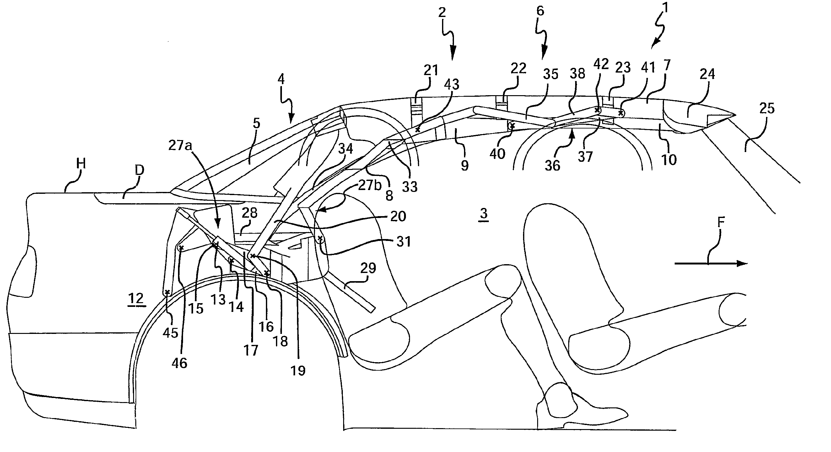
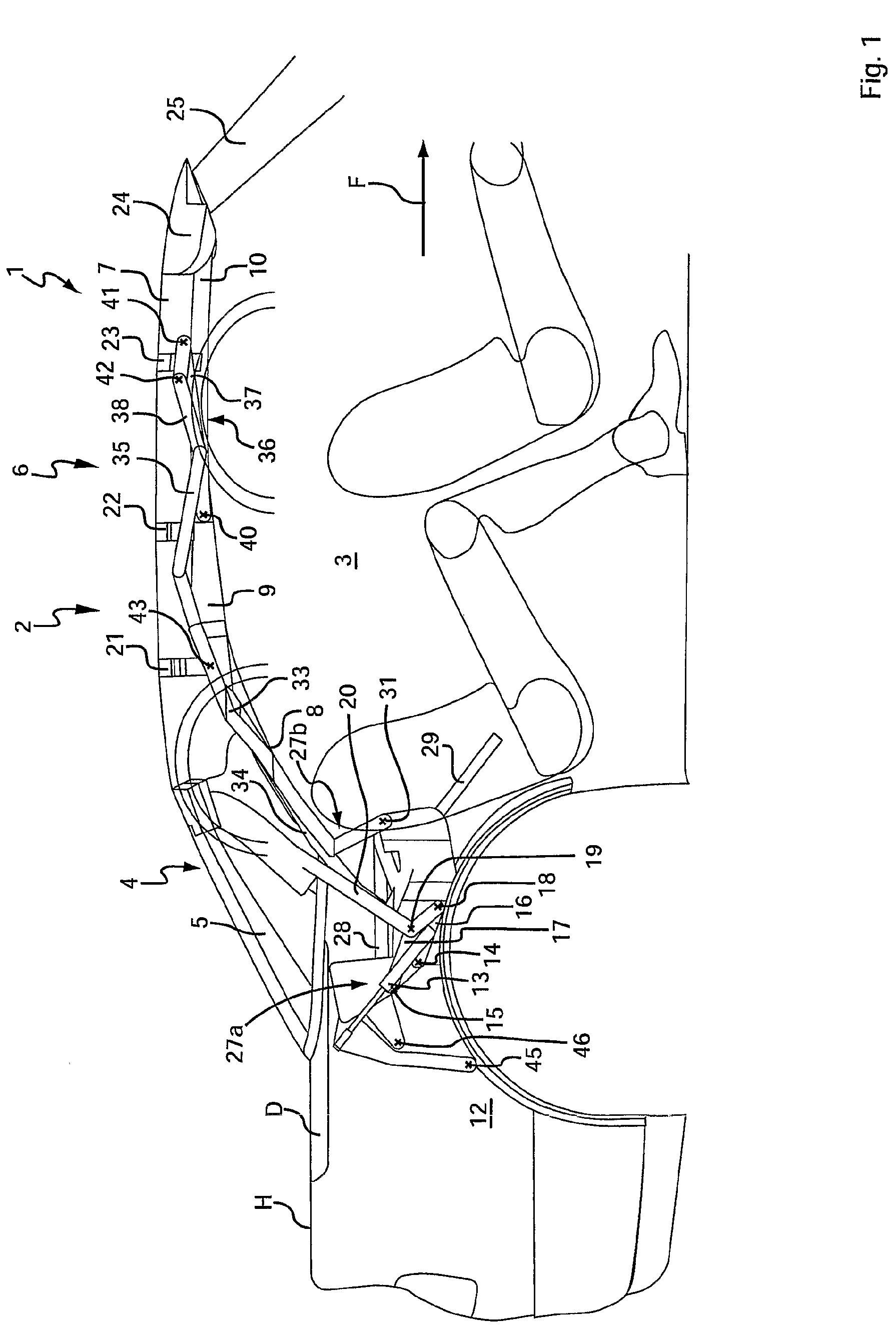
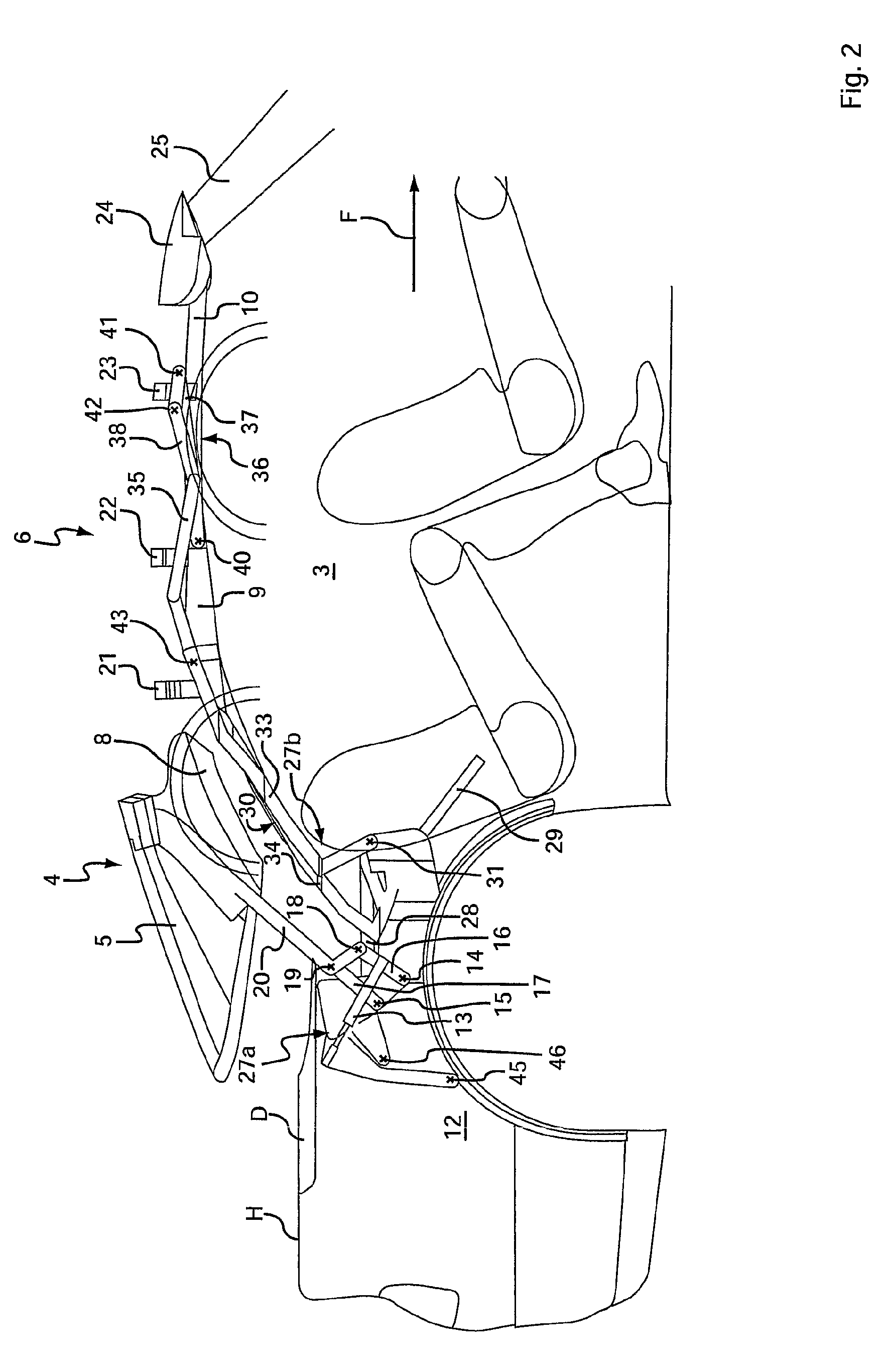
[0035]The convertible vehicle 1 according to the invention is shown schematically in the diagrams in its upper and middle areas, which include the passenger compartment 3. This can be covered by a movable roof 2, which is closed in the views according to FIG. 1 and FIG. 10.

[0036]The roof 2 includes a rigid rear roof area 4, which is designed dome-like and includes an arched rear window 5, which can be provided with a light- and / or heat-absorbing coating outside of a center transparent area, and can extend with its transverse edge 11 (shown in FIG. 6) into the lateral transverse outer edges of dome-like rigid rear roof area 4. A particularly good view to the rear is made possible by this.

[0037]The roof 2 also includes a front roof area 6 spanned with a covering 7 (only shown in FIG. 1 and FIG. 10). Several (for example, three here) lateral frame parts, connected to each other in the closed position with respect to the direction of travel F and running in the longitudinal direction of...


PUM


Abstract

A convertible vehicle with at least one front roof area, having a flexible covering in the direction of travel, and a rigid roof area, including a rear window. The front roof area includes several lateral frame parts lying one behind the other, which can be folded opposite to each other, at least in the essentially horizontal axes, and can be covered by the rear roof area in the stored position.

Description

CROSS-REFERENCE TO RELATED APPLICATION(S)[0001]This application is a US National Phase of International Application No. PCT / DE 2005 / 000487, filed Mar. 17, 2005, which claims priority to German 10 2004 01, filed Mar. 29, 2004, and German 10 2004 04, filed Oct. 1, 2004. The entire contents of the above identified applications are incorporated herein by reference.TECHNICAL FIELD[0002]The invention relates to a convertible vehicle with at least one flexible front and one rigid rear area.BACKGROUND OF THE INVENTION[0003]DE 101 40 232 A1 shows a convertible vehicle with a rigid rear roof part and a flexible roof area connected to it in the direction of travel, which includes a roof covering supported by several transverse convertible-top bows. The convertible-top bows are connected to each other in a known manner by lateral frame parts. These frame parts are pivoted around vertical axes opposite to each other for opening the flexible roof area. Several drives arranged on the corresponding...

Claims


Application Information

Patent Timeline
Patent Type & Authority Patents(United States)
IPC IPC(8): B60J7/12B60J1/18B60J7/20
CPCB60J1/1823B60J7/1265B60J7/201
Inventor MEINERT, STEFAN
Owner WILHELM KARMANN GMBH
Learn More