
System and method for electromagnetic pulse surface treatment

a technology of electromagnetic pulse and surface treatment, applied in the direction of electrical/magnetic/electromagnetic heating, soldering apparatus, manufacturing tools, etc., can solve the problems of difficult control, and difficult control of shot peening

Active Publication Date: 2008-03-13
GATEKEY ENG
View PDF7 Cites 2 Cited by
  • Summary
  • Abstract
  • Description
  • Claims
  • Application Information

AI Technical Summary

Benefits of technology

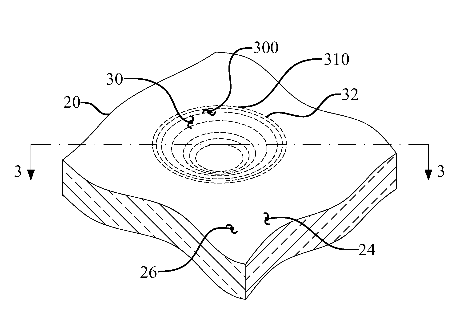
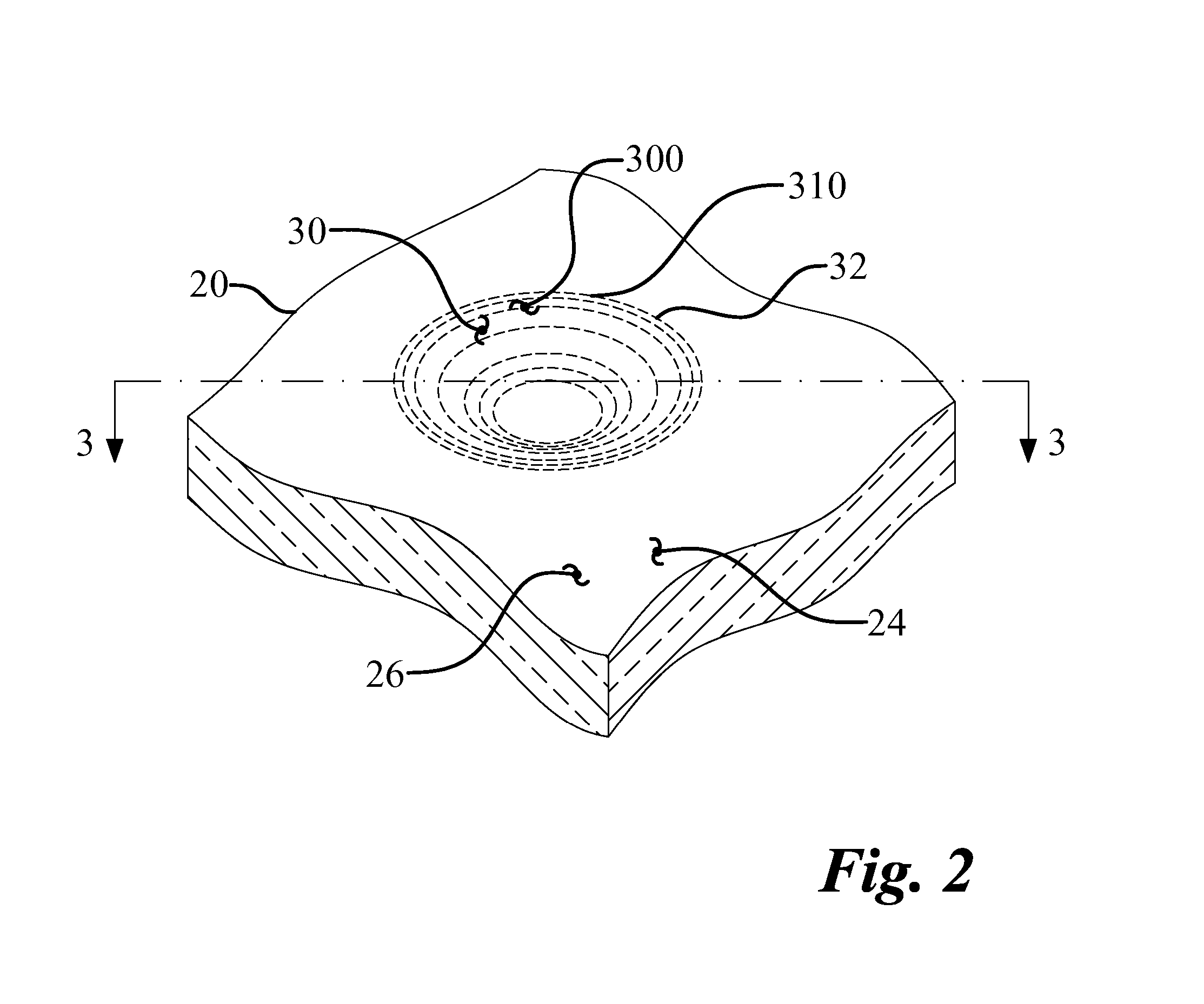
[0016] The indentation has an indentation perimeter. The system creates a treated surface having a treatment perimeter. In the embodiment where the system forms only one indentation, the treatment perimeter may be substantially the same as the indentation perimeter. The system may form multiple indentations in the treated surface. Then the treatment perimeter surrounds the treated surface. The system has a capability to form treated surfaces in localized areas, possibly in areas where tensile stresses are known to form, such as, treating welds and surface geometries which cause stress concentrations to form. Thus, the method may enhance the work piece's capability of enduring forces that cause tensile stress formation.
[0019] The impact transition region radius describes a curvature of the impact transition region. Again, the impact transition region radius may be described by a single radius. The lack of sharp transitions in the indentation or around the indentation perimeter reduce the stress concentrations.
[0030] The system may form individual indentations separated by relatively large indent spacing such that the indentations do not overlap. In one particular embodiment of the instant invention, the indent spacing separates the indentations by a distance which substantially prevents tensile stress from forming in the treated surface.
[0034] In another embodiment, the indent spacing is such that the residual compressive stress layer is continuous through the inter-indentation overlap region. Thus it is possible to create graduated stress profiles with the system. A desired level of stress may be achieved without forming stress concentrations by creating multiple overlapping indentations to target a desired overlap depth.

Problems solved by technology

Shot peening, however, is difficult to control and therefore provides inconsistent results.
Shot peening is difficult to control simply because the shot peening process has many process parameters.
Unfortunately, blasting tens of thousands of shot at the working surface does not, by itself, guarantee complete coverage.
To complicate the shot peening process even more, the shot breaks down during use.
As the shot breaks down, it becomes more difficult to control.
Shot breakdown may include normal wear and tear, and fracture.
Thus, shot breakdown lessens the repeatability of the treatment area topography and residual compressive stress layer.
Shot peening may damage the part.
In particular, shot peening may cause sharp topography to form.
So, rather than enhancing the part's performance, shot peening may lead to premature part failure.
In addition to the problems previously stated, shot peening is limited in other ways.
Also, any surface contamination on the part may interfere with shot impact, thus lessening the effects of the shot peening process.
In addition, using shot peening to treat small target areas without affecting surrounding areas is problematic.

Method used


Image

  • System and method for electromagnetic pulse surface treatment
  • System and method for electromagnetic pulse surface treatment
  • System and method for electromagnetic pulse surface treatment

Examples


Embodiment Construction

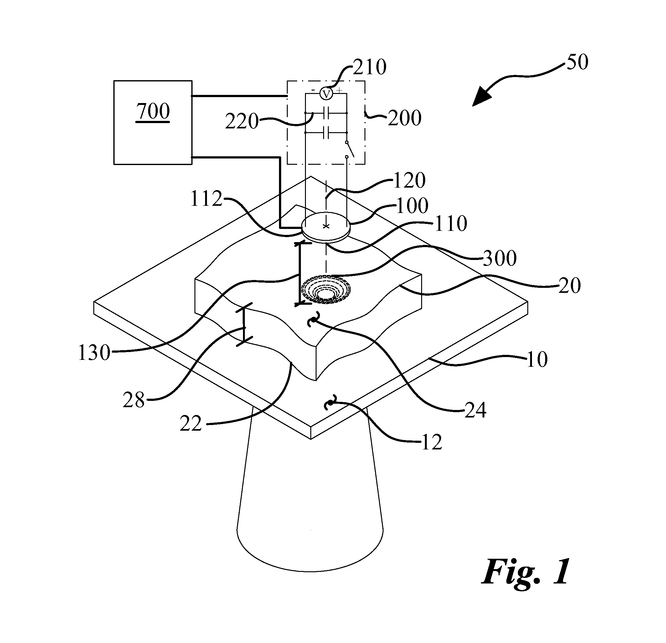
[0072] A system (50) and method for electromagnetic pulse surface treatment of the present invention enables a significant advance in the state of the art. The embodiments of the system accomplish this by new and novel methods that are configured in unique and novel ways and which demonstrate previously unavailable but preferred and desirable capabilities. The description set forth below in connection with the drawings is intended merely as a description of the present embodiments of the invention, and is not intended to represent the only form in which the present invention may be constructed or utilized. The description sets forth the designs, functions, means, and methods of implementing the invention in connection with the illustrated embodiments. It is to be understood, however, that the same or equivalent functions and features may be accomplished by different embodiments that are also intended to be encompassed within the spirit and scope of the invention.

[0073] In one embod...


PUM

PropertyMeasurementUnit
region radiusaaaaaaaaaa
radiusaaaaaaaaaa
overlap radiusaaaaaaaaaa

Abstract

A system and method for electromagnetic surface treatment of a work piece has an electromagnetic pulse generator and an electromagnetic pulse tool. The work piece has a working surface. A current pulse generated by the electromagnetic pulse generator travels through the tool producing an electromagnetic pulse. The electromagnetic pulse interacts with the working surface causing an indentation to form. A residual compressive stress layer is also formed. The indentation has a smooth and continuous topography that is described by an indentation perimeter, an indentation transition region, an indentation sidewall, an impact transition region, and an impact region. The method may also simultaneously, or subsequently, form a second indentation which overlaps with the indentation. An inter-indentation overlap region is formed when the indentations overlap. The inter-indentation overlap region is smooth and continuous. Multiple treated surfaces may easily be formed on the working surface of the work piece.

Description

CROSS REFERENCE TO RELATED APPLICATIONS [0001] This application is a division of U.S. patent application Ser. No. 11 / 651,138 filed on Jan. 9, 2007, which claims the benefit of U.S. provisional patent application Ser. No. 60 / 758,094 filed Jan. 11, 2006, the disclosures of which are incorporated by reference as if completely written herein.STATEMENT REGARDING FEDERALLY SPONSORED RESEARCH OR DEVELOPMENT [0002] This invention was not made as part of a federally sponsored research or development project. TECHNICAL FIELD [0003] The present invention relates to the field of electromagnetic pulse surface treatment for enhanced fatigue performance, and more particularly, to a method and system for forming an indentation in a work piece with an electromagnetic pulse such that the indentation has smooth and continuous transition regions. BACKGROUND OF THE INVENTION [0004] It is well known that cold working a surface of a metallic part will cause a residual compressive stress layer to form. The...

Claims


Application Information

Patent Timeline
Patent Type & Authority Applications(United States)
IPC IPC(8): B23K26/00B23P9/00
CPCC21D7/06Y10T428/12993H05B6/101Y02P10/25
Inventor DYDO, JAMES R.YUSHANOV, SERGEI P.
Owner GATEKEY ENG
Learn More