
Connection point

a technology of connecting points and connecting parts, applied in the direction of bolts, turning machine accessories, supporters, etc., can solve the problem of often not optimal connection between the two tool parts, and achieve the effect of convenient placemen

Inactive Publication Date: 2005-06-14
MAPAL FAB FUR PRAZIONSWERKZEUGE DR KRESS KG
View PDF13 Cites 27 Cited by
  • Summary
  • Abstract
  • Description
  • Claims
  • Application Information

AI Technical Summary

Benefits of technology

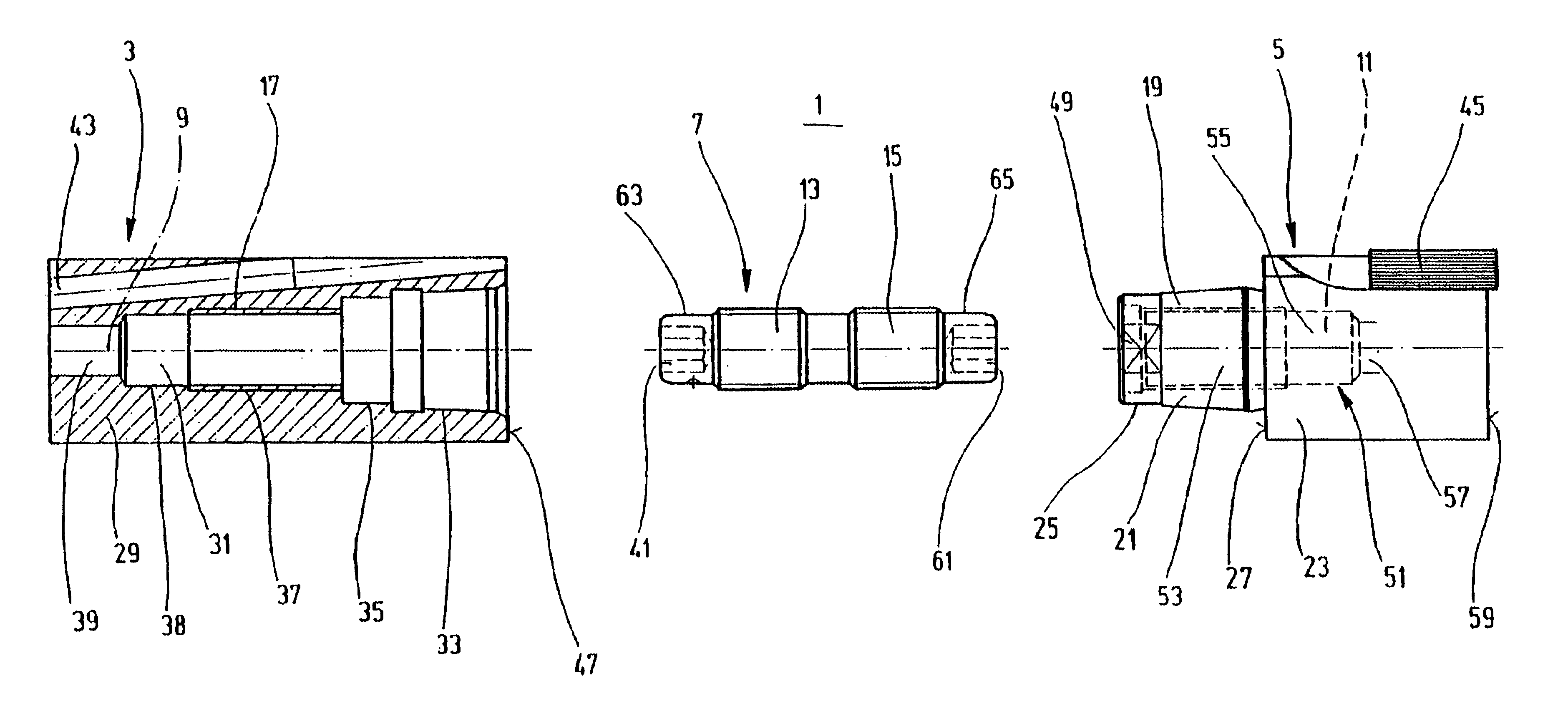
[0004]The task of the invention therefore is to create a connection point between two tools in which a defined tension of the two parts can be ensured. For solving this task, a connection point is proposed which has the features mentioned in claim 1. It is distinguished in that the threaded spindle serving to connect the two tool parts has, at least in an end area, a projection which can engage in a threaded section which is provided in the associated tool part. For this purpose, the projection is provided with an outside diameter that is smaller than the interior diameter of the associated threaded area. Upon connecting of two tool parts, the threaded spindle can be inserted in one of the parts, so that the projection engages with the threaded area of the tool part and the threaded spindles are arranged in a defined starting position and if needed may also be held. While the threaded spindle thus is inserted into the first tool part and is retained in a defined position, the second tool part can be placed on the first tool part and the threaded spindle can be caused to rotate. Thus the opposing threaded sections of the threaded spindle engage in the associated threaded areas of the tool parts so that they are pressed firmly against each other and are connected together. Upon connecting the two tool parts, the threaded spindle is arranged as a result of the projection in a defined position. It therefore is not necessary to screw it at least somewhat into the first threaded part and to retain it there securely before the second tool part is placed on the first. Thus a defined starting position of the threaded spindle and a specified tension in the area of the connection point is established.
[0005]Especially preferred is an exemplary embodiment of the connection point in which the threaded spindle is provided with a projection on each end which engages in the associated threaded area of the tool parts to be connected to each other. For this purpose it is also provided here that the outside diameter be configured smaller than the interior diameter of the associated threaded area. As a result of the projections provided at both ends of the threaded spindle, the tools can be easily placed one on the other with it being ensured on both sides that the threaded spindle assume a defined initial position.

Problems solved by technology

It has been found that the connection of the two tool parts often is not optimal because prior to assembly of the two tool parts, the threaded spindle is screwed into one of the tool parts to a greater or lesser distance and thus no defined tension can be generated.

Method used


Image

  • Connection point
  • Connection point

Examples


Embodiment Construction

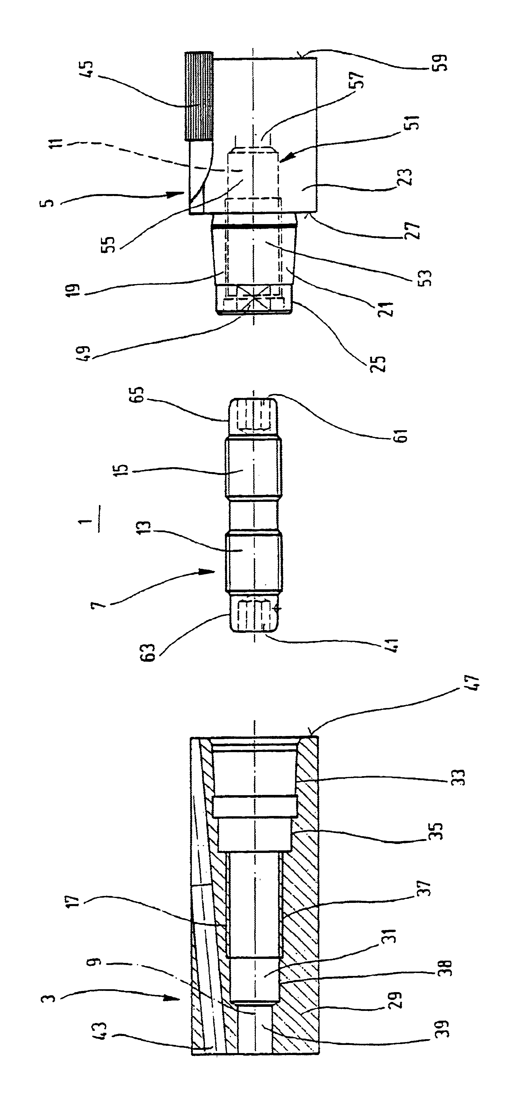
[0007]Connection point 1 depicted in the FIGURE has a first tool part which is here configured as tool holder 3, and a second tool part that here is configured as tool head 5. Between the two tool parts, i.e., between tool holder 3 and tool head 5 is situated a threaded spindle 7, which is oriented in the longitudinal direction of the tool parts, here coaxially to middle axis 9 of tool holder 3 and to middle axis 11 of tool head 5. Threaded spindle has two oppositely threaded sections 13 and 15 which are configured as exterior threads and interact with the threaded areas 17 and 19 configured as interior threads in tool holder 3 and tool head 5, respectively. Tool head 5 has a preferably conically configured projection, also designated retaining cone, 21 which tapers from the base body 23 of the tool head toward the left and transitions into a cylindrical section 25. Provided at base body 23 is a bearing surface 27 that encircles projection 21.

[0008]Correspondingly, tool holder 3 or ...


PUM

PropertyMeasurementUnit
Diameteraaaaaaaaaa
Areaaaaaaaaaaa

Abstract

A connection point (1) between two tool parts is proposed which are joined by means of a threaded spindle (7) oriented in longitudinal direction of the tool parts. The threaded spindle has two oppositely threaded sections (13, 15) which interact with two threaded areas (17, 19) in the tool parts. The connection point (1) is distinguished in that at least one end area of the threaded spindle (7) has a shoulder (63), the outside diameter of which is smaller that the interior diameter of the associated threaded area (17).

Description

[0001]The invention concerns a connection point between two tools according to the precharacterizing clause of claim 1.[0002]Connection points of the type referred to here are known. They serve to connect two tool parts together, for example a tool holder which can be a direct part of a machine tool or can in turn be brought into a machine tool and fastened there, to a tool head; a tool holder to an intermediate part; two intermediate parts to each other, and / or an intermediate part to a tool head. In order to connect the tool parts, a threaded spindle is used which is provided with oppositely threaded sections. These engage in threaded sections of the tool parts to be connected to each other. Upon a rotating movement of the threaded spindle, the two tool parts are firmly connected to each other since the threaded spindle draws the tool parts together so that they securely contact each other.[0003]It has been found that the connection of the two tool parts often is not optimal becau...

Claims


Application Information

Patent Timeline
IPC IPC(8): B23B31/10B23B31/11B23C5/10B23Q3/12F16B1/00F16B23/00F16B35/00
CPCB23B31/1107B23B31/1122B23C5/10B23C2210/03Y10T403/7171Y10T403/553Y10T403/556Y10T279/15Y10T403/68Y10T403/55Y10T403/5733Y10T403/5746Y10T409/30952F16B1/00
Inventor KRESS, DIETERHABERLE, FRIEDERICH
Owner MAPAL FAB FUR PRAZIONSWERKZEUGE DR KRESS KG
Learn More