Terminal board having a first fastening member accommodated in a chamber

a technology of fixing member and clamping member, which is applied in the direction of clamping/spring connection, electrical equipment, connections, etc., can solve the problems of deterioration of assembling workability, high production cost, and deterioration of bonding strength, so as to prevent deterioration of waterproof performance due to distortion and breakdown of components and enhance assembling workability

Active Publication Date: 2005-06-14
YAZAKI CORP
View PDF3 Cites 18 Cited by
  • Summary
  • Abstract
  • Description
  • Claims
  • Application Information

AI Technical Summary

Benefits of technology

[0009]It is therefore an object of the invention to provide a terminal board in which a difference in height between the terminal board and a connecting member can be absorbed if the difference exists, so tha...

Problems solved by technology

There is such a problem that in a case where the upper end face of the nut is not projected from the terminal board, the nut will be unable to establish an electric connection with the terminals, or alternatively, in a case where the upper end face is projected too much, a bonding length between the nut and the terminal board will be short, resulting in deterioration of bonding strength.
A height of the nut with respect to the board body must be adjusted with high precision when manufactured, and it is a problem that high production cost would be required.
In a case where the square nut 31 which has been fixed to the terminal board 30 by insert molding, heat pressure fitting, pressure fitting, etc is projected from an upper face of the terminal board 30 as shown in FIG. 12, there is such a problem that the terminal metal 38 of the motor cable 36 which has been inserted through the insertion hole 39 at the side area may inter...

Method used


Image

  • Terminal board having a first fastening member accommodated in a chamber
  • Terminal board having a first fastening member accommodated in a chamber
  • Terminal board having a first fastening member accommodated in a chamber

Examples


Embodiment Construction

[0038]Preferred embodiments of the invention will be described below in detail with reference to the accompanying drawings.

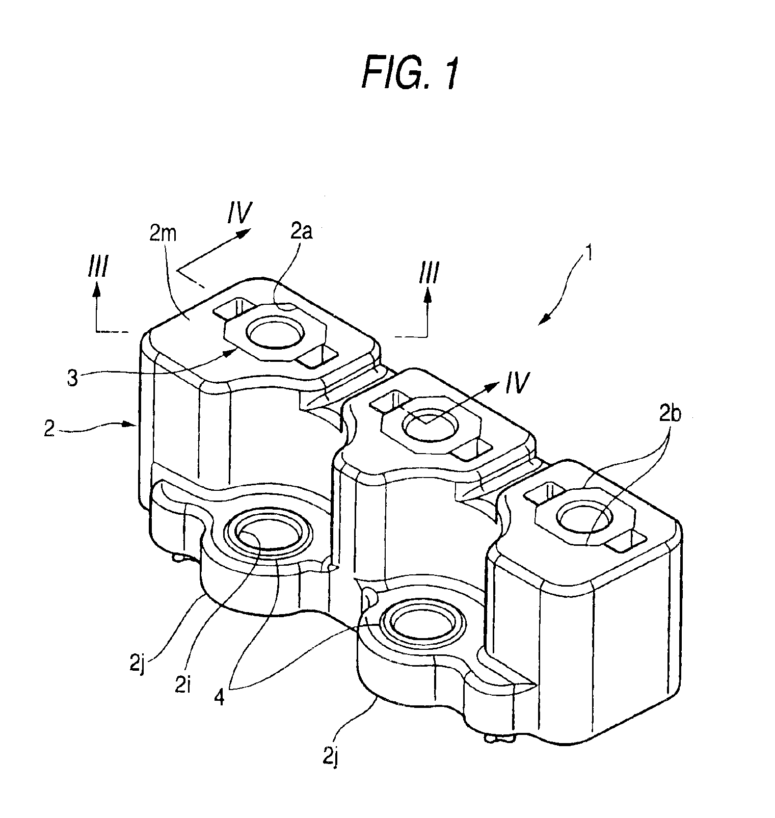
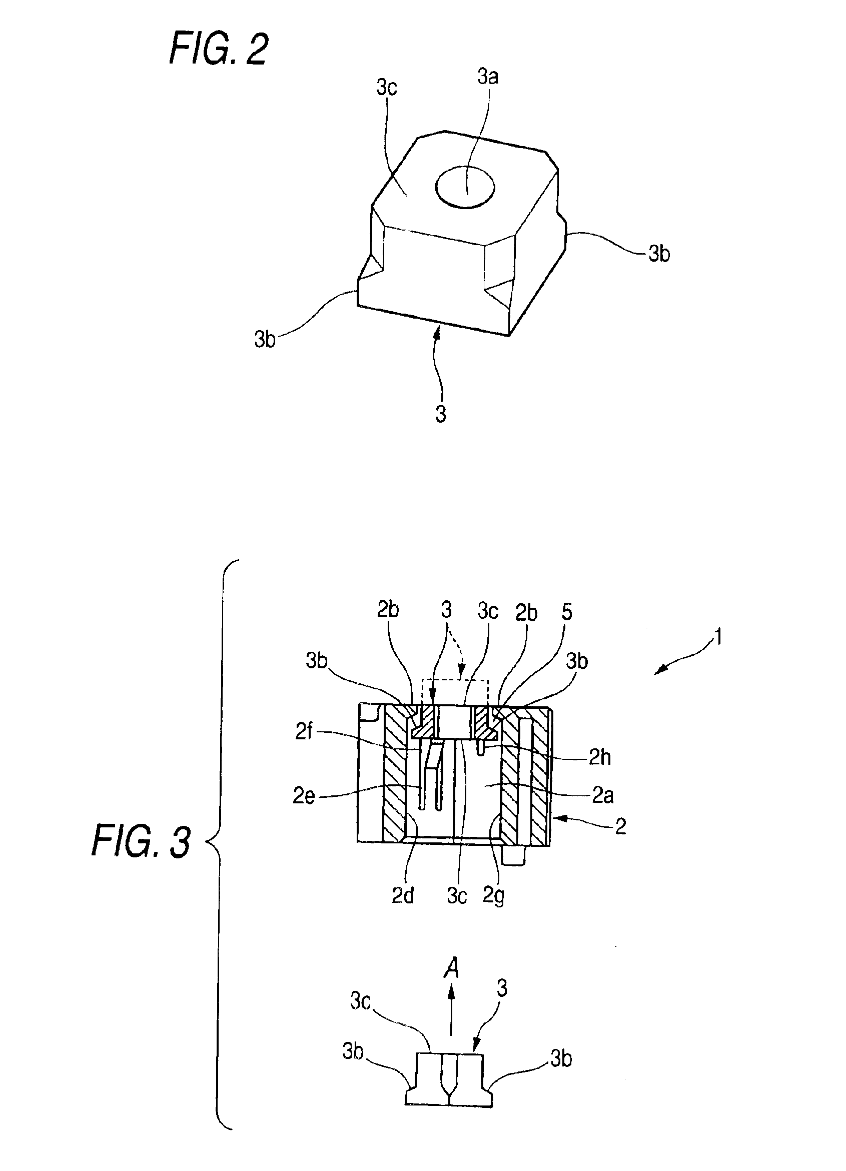
[0039]As shown in FIGS. 1 to 3, a terminal board 1 comprises a board body 2 and a square nut 3. The board body 2 is formed of synthetic resin by injection molding into a roughly rectangular parallelepiped shape, and three nut chambers 2a are formed as through holes passing through the terminal board 2 in a vertical direction. In each of the nut chambers 2a, the hole is formed as a square-shaped hole slightly larger than the square nut 3 which will be described below, so that the square nut 3 can be inserted and accommodated therein. Moreover, as shown in FIG. 5, the nut chamber 2a is provided, at an upper end thereof, with retainers 2b so that the nut chamber 2a has a substantially octagonal shape at its upper end.

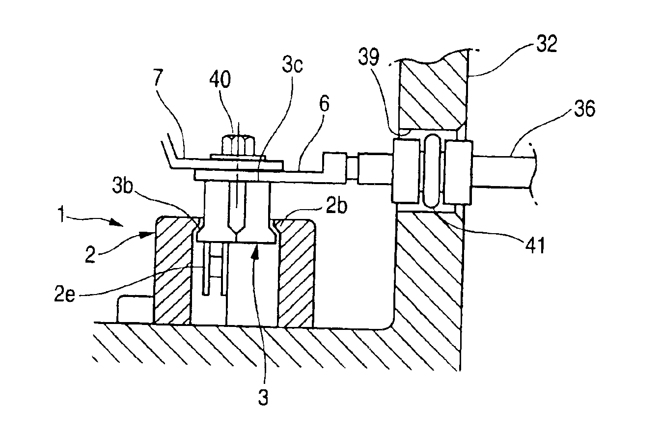
[0040]As shown in FIGS. 3 and 4, a pair of lances 2e are formed in a cantilever manner on a pair of inner walls 2d of the nut chamber 2a which are opp...


PUM


Abstract

In a terminal board, at which a first connecting member of a power feeding side and a second connecting member of a power receiving side are electrically connected, a board body is formed with a chamber and an opening continued from the chamber. A first fastening member has a contact portion, and is accommodated in the chamber to fasten the first connecting member and the second connecting member on the contact portion with a second fastening member along a fastening axis. The first fastening member is movable in the chamber in a first direction parallel to the fastening axis, so that the contact portion is projected from the opening in accordance with a fastening operation of the first connecting member and the second connecting member.

Description

BACKGROUND OF THE INVENTION[0001]The present invention relates to a terminal board, and more particularly, to a terminal board which is suitable for use with components or the like to which a motor power source of an electric vehicle is to be connected.[0002]As a first related-art terminal board, Japanese Patent Publication No. 11-144783A discloses a terminal board which includes a board body formed of synthetic resin and a nut embedded in the board body by insert molding, to which two terminals superposed one on another is fixed with a bolt (cf., Pages 2-3 and FIG. 1).[0003]As a second related-art terminal board, Japanese Patent Publication No. 2001-251089A discloses a terminal board which is provided inside a shield case made of aluminum die casting for connecting a terminal of a motor cable to a motor of an electric vehicle (cf., Pages 3-4 and FIG. 1).[0004]In the first related-art terminal board, the nut is embedded by insert molding in such a manner that an upper end face of th...

Claims


Application Information

Patent Timeline
IPC IPC(8): H01R4/28H01R9/00H01R4/30H01R9/22H01R9/18H01R4/38
CPCH01R4/30H01R9/223H01R9/18
Inventor IKEDA, TOMOHIRO
Owner YAZAKI CORP
Why Eureka
Try Eureka