Method and apparatus for manufacturing image displaying apparatus

a technology of image displaying apparatus and manufacturing method, which is applied in the manufacture of electrode systems, electric discharge tubes/lamps, instruments, etc., can solve the problems of long manufacturing process time and unsuitability, and achieve the effect of reducing vacuum exhaust time, high vacuum degree, and improving manufacturing efficiency

Inactive Publication Date: 2005-06-14
CANON KK
View PDF27 Cites 7 Cited by
  • Summary
  • Abstract
  • Description
  • Claims
  • Application Information

AI Technical Summary

Benefits of technology

[0013]It is an object of the present invention to enable to easily attain reduction of vacuum exhaust time and high vacuum degree in manufacturing an image displaying apparatus, thereby improving efficiency of manufacturing.

Problems solved by technology

The manufacturing method according to the conventional art described above requires considerably long time for manufacturing one display panel, thus is not suitable for manufacturing a display panel inside of which requires the vacuum degree of 1×10⁻⁶ Pa or more.
Due to these reasons, manufacturing process time is long.

Method used


Image

  • Method and apparatus for manufacturing image displaying apparatus
  • Method and apparatus for manufacturing image displaying apparatus
  • Method and apparatus for manufacturing image displaying apparatus

Examples


Embodiment Construction

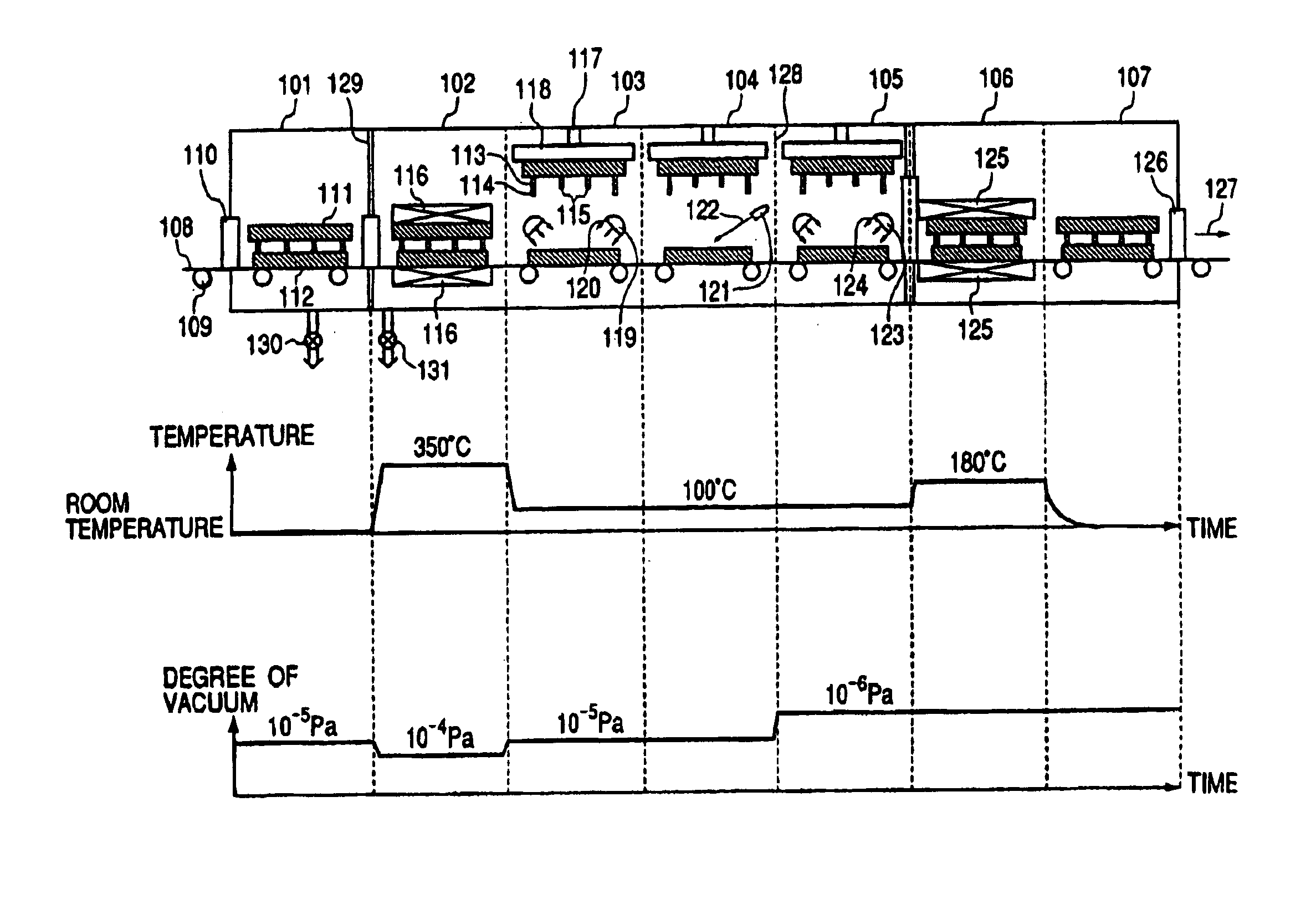
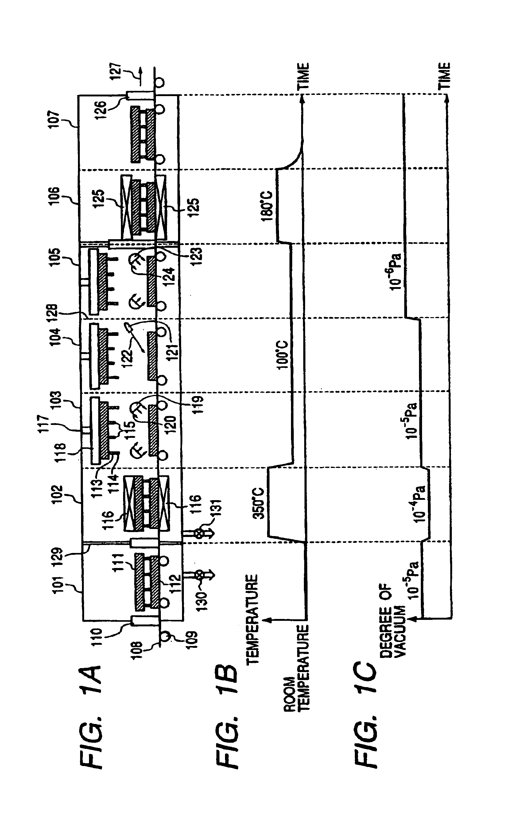
[0039]First, the present invention is a method of manufacturing an image displaying apparatus, which is characterized by comprising the steps of:

[0040]a: preparing a first substrate on which phosphor exciting means is disposed and a second substrate on which phosphors emitting light by the phosphor exciting means under the vacuum atmosphere;

[0041]b: carrying one or both of the first and the second substrates into a getter processing chamber in the vacuum atmosphere under the vacuum atmosphere, and subjecting to getter processing the one substrate carried or one or both of the substrates carried; and

[0042]c: carrying the first and the second substrates in a seal processing chamber in the vacuum atmosphere under the vacuum atmosphere, and heat sealing the substrates in an opposing state.

[0043]Secondly, the present invention is a method of manufacturing an image displaying apparatus, which is characterized by comprising the steps of:

[0044]a: preparing a first substrate on which phospho...


PUM


Abstract

A method and an apparatus for manufacturing an image displaying apparatus having a display panel. A first substrate of the display panel on which a phosphor exciter is disposed and a second substrate of the display panel on which phosphors emitting light by the phosphor exciter is provided, are prepared under a vacuum atmosphere. Then, the first and the second substrates are carried in a getter processing chamber or bake processing chamber, and getter processing or bake processing is applied thereto under the vacuum atmosphere. After the processing, the first and the second substrates are carried in a seal processing chamber, where the substrates are heat sealed under the vacuum atmosphere. Thus, reduction of vacuum exhaust time and a high vacuum degree in manufacturing an image displaying apparatus is attained and efficiency of manufacturing is improved.

Description

BACKGROUND OF THE INVENTION[0001]1. Field of the Invention[0002]The present invention relates to an image displaying apparatus in which electron-emitting devices are arranged in matrix, more particularly to a method and an apparatus for manufacturing an image displaying apparatus having a display panel on which a rear plate (RP) provided with electron-emitting devices arranged in matrix and a face plate (FP) provided with phosphors are arranged in opposing positions as a first image forming member and as a second image forming member, respectively.[0003]2. Related Background Art[0004]Conventionally, an electron-emitting device is roughly divided into two known types, i.e., a thermal electron-emitting device and a cold-cathode electron-emitting device. The cold-cathode electron-emitting device includes the field emission type (hereinafter referred to as the FE type), the metal / insulation layer / metal type (hereinafter referred to the MIM type), the surface conducting type electron-emi...

Claims


Application Information

Patent Timeline
Patent Type & Authority Patents(United States)
IPC IPC(8): H01J9/48H01J9/00H01J9/38H01J9/18H01J9/39H01J9/26H01J9/40H01J9/46
CPCH01J9/18H01J9/38H01J9/48H01J9/46H01J2329/00G07F11/24G07F5/02G07F9/10
Inventor MIYAZAKI, TOSHIHIKONAKATA, KOHEIKANEKO, TETSUYA
Owner CANON KK
Why Eureka
Try Eureka