
Abrasive flow machining apparatus and method

a technology of flow machining and machining apparatus, which is applied in the direction of manufacturing tools, grinding machine components, edge grinding machines, etc., can solve the problems of uniform temperature distribution throughout the media, adversely affecting the system capability, and excessively high temperatures

Inactive Publication Date: 2005-06-14
EXTRUDE HONE CORP
View PDF7 Cites 17 Cited by
  • Summary
  • Abstract
  • Description
  • Claims
  • Application Information

AI Technical Summary

Benefits of technology

[0010]A third embodiment of the subject invention is directed to a method for abrasive flow machining using an abrasive media through the orifice of a workpiece, wherein the orifice defines an upstream side and a downstream side. The method comprises the steps of moving media through the orifice from the upstream side to the downstream side at a predetermined constant pressure on a first side and selectively throttling the flow of media to the downstream side to control the flow rate of the media passing through the orifice while maintaining the predetermined constant pressure on a second side.
[0011]A fourth embodiment of the subject invention is directed to a method for abrasive flow machining using an abrasive media through the orifice of a workpiece, wherein the orifice defines a first side and a second side. The method comprises the steps of moving media through the orifice from the first side to the second side at a predetermined constant pressure selectively throttling the flow of media to the second side to control the flow rate of the media passing through the orifice while maintaining the predetermined constant pressure moving media through the orifice from the second side to the first side at the predetermined constant pressure and selectively throttling the flow of media to the first side to control the flow rate of the media passing through the orifice while maintaining the predetermined constant pressure.

Problems solved by technology

Conventional abrasive flow machining processes are designed to maintain a constant media extrusion pressure which often results in significant changes in media temperature, flow rate and viscosity which adversely impacts the system capability to accurately predict abrasive flow machine (AFM) processing times and, consequently, overall process results.
This produces both excessively high temperatures and a non-uniform temperature distribution throughout the media.
High temperatures and variations in temperatures throughout the media prevent the media from working in a consistent and effective fashion.

Method used


Image

  • Abrasive flow machining apparatus and method
  • Abrasive flow machining apparatus and method
  • Abrasive flow machining apparatus and method

Examples


Embodiment Construction

[0021]In one embodiment of the subject invention abrasive media is subjected to a constant pressure and forced through an orifice of a workpiece. The flow rate discussed with this embodiment will be equal to or less than the maximum flow rate capability with the downstream side of the orifice open to the atmosphere. In particular, a flow rate of less than this maximum value is obtained by limiting the flow of the media at the down stream side of the orifice.

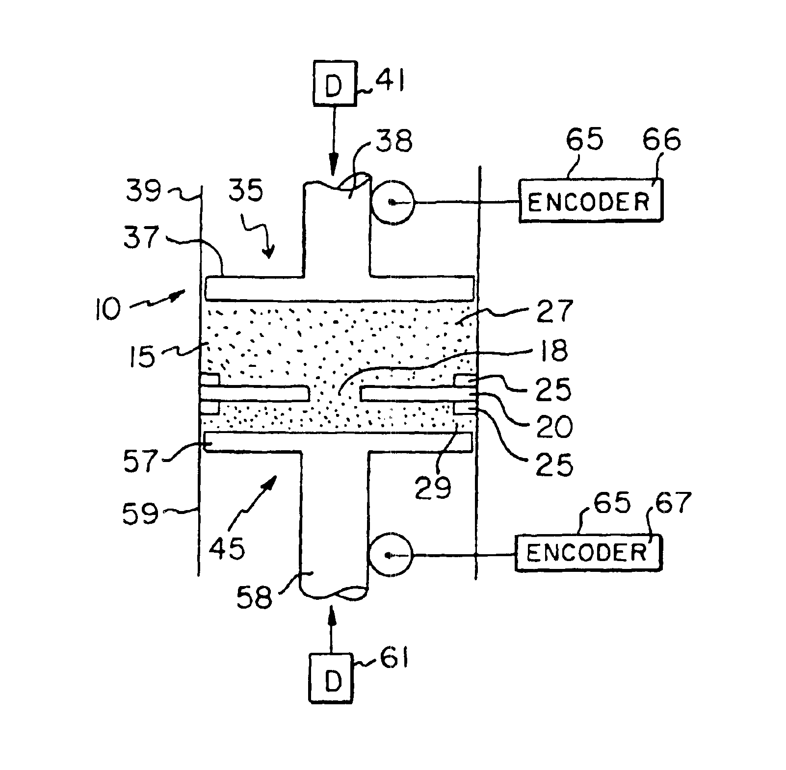
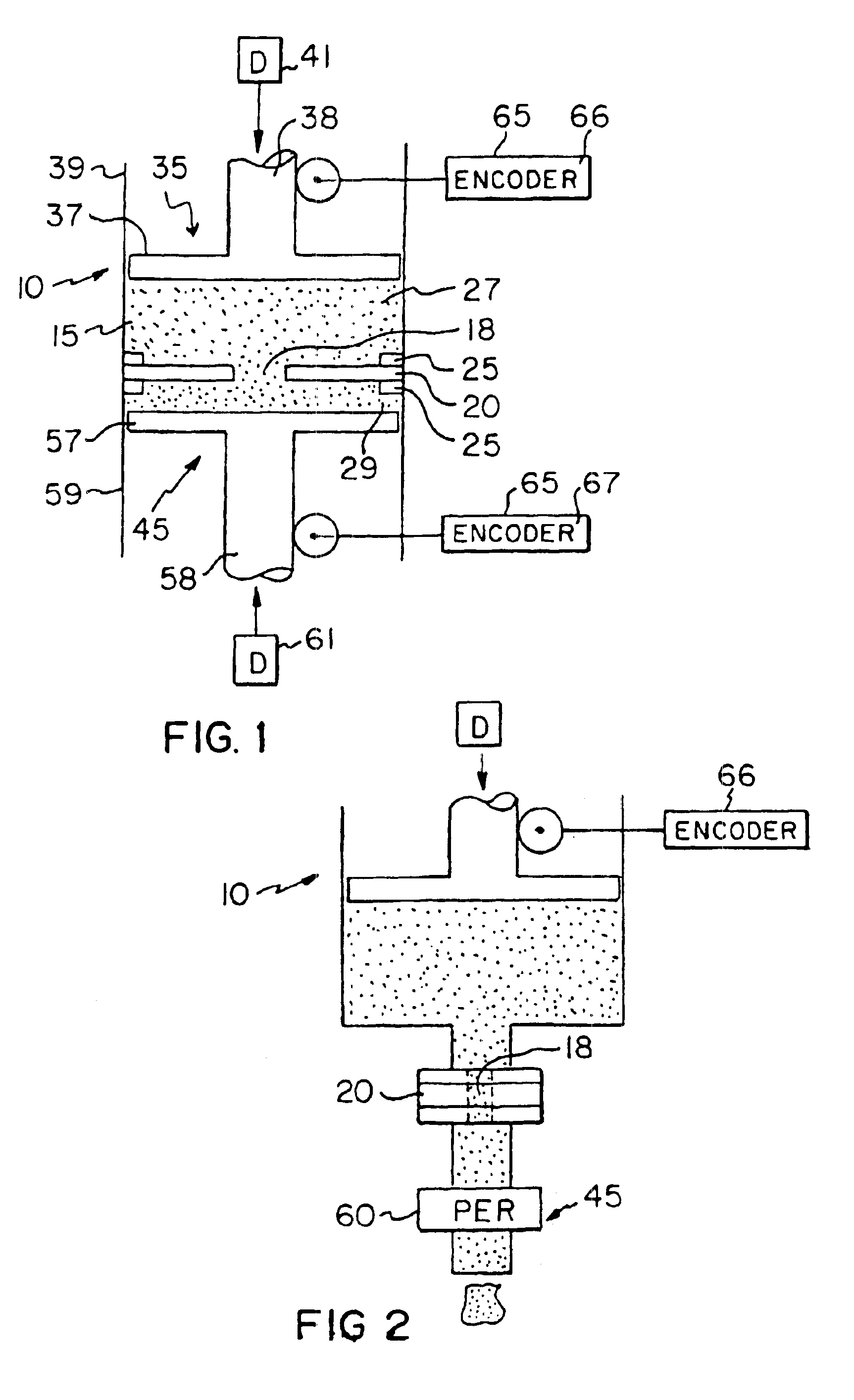
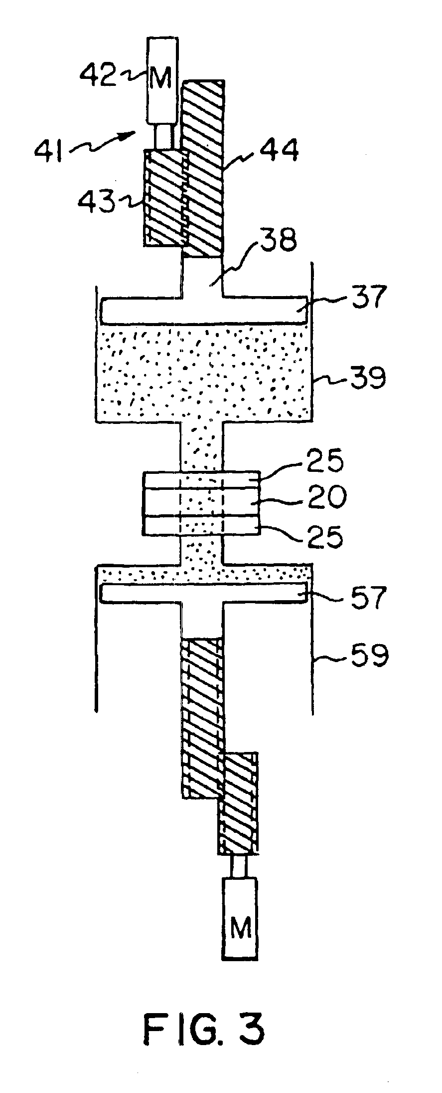
[0022]Directing attention to FIG. 1, a simplified schematic of an abrasive flow machine 10 for moving abrasive media 15 through the orifice 18 of a workpiece 20 is illustrated. For purposes of this discussion, media will be discussed as having viscosity in the range between 1 to 50 million centipoise. One example of a relatively high viscosity media is a visco-elastic plastic media such as a semisolid polymer composition. One example of a media having a lower viscosity is a liquid abrasive slurry that includes abrasives suspended...


PUM

PropertyMeasurementUnit
viscosityaaaaaaaaaa
pressureaaaaaaaaaa
flow rateaaaaaaaaaa

Abstract

An apparatus and method for abrasive flow machining the orifice (18) of a workpiece (20) by using an abrasive media (15) whereby the apparatus (10) is capable of passing media (15) through the orifice (18) at a predetermined pressure and at a constant flow rate. In the alternative, the apparatus (10) is capable of passing media (15) through the orifice (18) at a fixed flow rate by using variable pressure upon the media (15) through the orifice (18).

Description

BACKGROUND OF THE INVENTION[0001]1. Field of the Invention[0002]The invention is related to abrasive flow machining and, more particularly, to an abrasive flow machining apparatus capable of processing an orifice within a part by carefully controlling the media flow rate. The invention is also directed to a method for such processing.[0003]2. Description of the Related Art[0004]Abrasive flow machining is the process of polishing or abrading a workpiece by passing a viscous media having abrasive particles therein under pressure over the workpiece or through an orifice extending through the workpiece.[0005]Conventional abrasive flow machining processes are designed to maintain a constant media extrusion pressure which often results in significant changes in media temperature, flow rate and viscosity which adversely impacts the system capability to accurately predict abrasive flow machine (AFM) processing times and, consequently, overall process results.[0006]As an example, the media t...

Claims


Application Information

Patent Timeline
Patent Type & Authority Patents(United States)
IPC IPC(8): B24B31/00B24B31/116B24B49/16
CPCB24B49/16B24B31/116B24B31/006
Inventor WALCH, WILLIAM L.
Owner EXTRUDE HONE CORP
Learn More