Spindle motor control using a current profile to taper current transitions

a spindle motor and current profile technology, applied in the direction of motor/generator/converter stopper, dynamo-electric converter control, instruments, etc., can solve problems such as unstable power supply condition, power supply especially vulnerable, and parasitic current that overheats and damages the devi

Inactive Publication Date: 2005-06-14
SEAGATE TECH LLC
View PDF29 Cites 34 Cited by
  • Summary
  • Abstract
  • Description
  • Claims
  • Application Information

AI Technical Summary

Problems solved by technology

Negative voltage that exceeds more than a diode voltage drop can create a parasitic current that overheats and damages the device.
Also, sinking current into the power supply can cause an unstable condition in the power supply.
Since power supplies are designed for minimum capacitance to keep costs down, power supplies are especially vulnerable.
Voltage generated by a transient condition can easily exceed the limits in which the voltage supply breaks down.

Method used


Image

  • Spindle motor control using a current profile to taper current transitions
  • Spindle motor control using a current profile to taper current transitions
  • Spindle motor control using a current profile to taper current transitions

Examples


Embodiment Construction

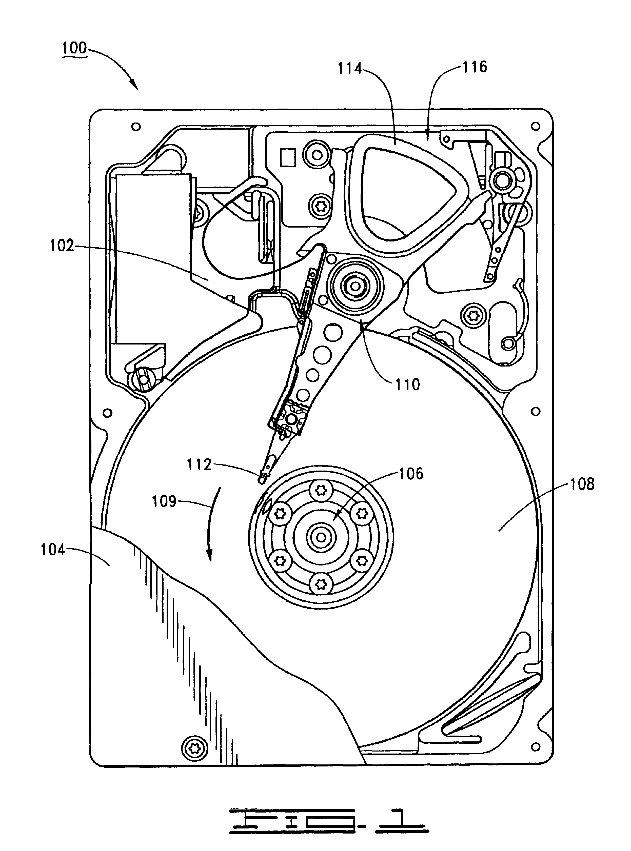
[0024]FIG. 1 provides a top plan view of a disc drive 100 constructed in accordance with preferred embodiments of the present invention. A base deck 102 and a top cover 104 (shown in partial cutaway) cooperate to form a sealed housing for the disc drive 100. A spindle motor 106 rotates a number of magnetic recording discs 108 in a rotational direction 109. An actuator assembly 110 supports an array of read / write heads 112 adjacent the respective disc surfaces. The actuator assembly 110 is rotated through the application of current to an actuator coil 114 of a voice coil motor (VCM) 116.

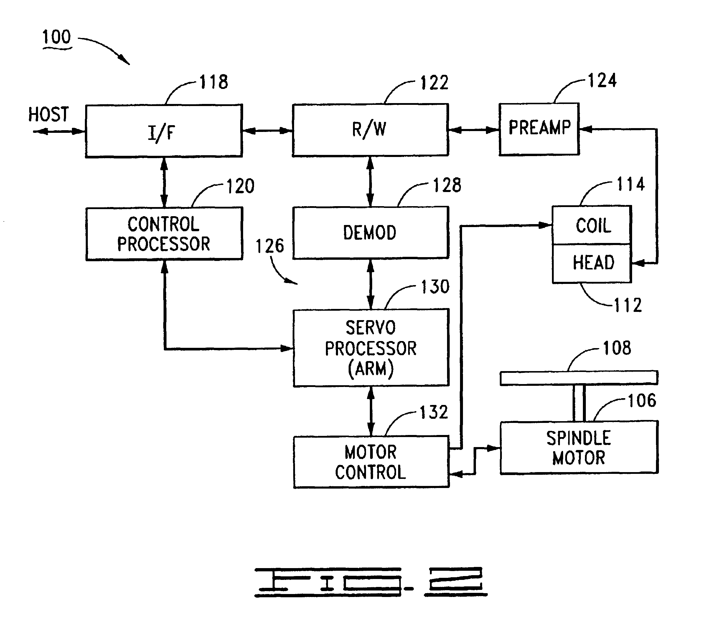
[0025]FIG. 2 provides a functional block diagram of the disc drive 100. FIG. 2 includes control circuitry provided on a disc drive printed circuit board (PCB) affixed to the underside of the disc drive 100, and thus not visible in FIG. 1.

[0026]Data and host commands are provided from a host device to the disc drive 100 using interface (I / F) circuitry 118 in conjunction with a top level control process...


PUM

PropertyMeasurementUnit
frequencyaaaaaaaaaa
voltageaaaaaaaaaa
elapsed timeaaaaaaaaaa

Abstract

Method and apparatus for operating a motor. During a commutation state current is applied to a motor while field effect transistors (FETs) are held in an enable or disable state to effect current in phases of the motor. The phases have a high FET and a low FET. Control circuitry is employed to detect back electromotive force and zero crossing (Zc) signals that indicate transition timing for the commutation states. At a transition state the current is decreased in accordance with a noninstaneous decay function and applying a pulse width modulated signal to a switching element. Alternatively, the current is decreased by enabling either all low side FETs or all high side FETs to allow the current to decay. The next commutation state is applied after the current has been reduced, avoiding negative current to be source from ground and reducing current spikes in the motor.

Description

RELATED APPLICATIONS[0001]This application claims priority to U.S. Provisional Application No. 60 / 337,266 filed Nov. 5, 2001.FIELD THE INVENTION[0002]The claimed invention relates generally to the field of disc drive data storage devices and more particularly, but not by way of limitation, to a method and apparatus for operating a disc drive spindle motor.BACKGROUND[0003]A disc drive is a data storage device used to store digital data. A typical disc drive includes a number of rotatable magnetic recording discs that are axially aligned and mounted to a spindle motor for rotation at a high constant velocity. A corresponding array of read / write heads access tracks defined on the respective disc surfaces to write data to and read data from the discs.[0004]Disc drive spindle motors are typically provided with a three-phase, direct current (dc) brushless motor configuration. The phase windings are arranged about a stationary stator on a number of radially distributed poles. A rotatable s...

Claims


Application Information

Patent Timeline
Patent Type & Authority Patents(United States)
IPC IPC(8): G11B19/28H02P6/00H02P6/12
CPCG11B19/28H02P6/12H02P6/002H02P6/28
Inventor HUSSEIN, HAKAM D.
Owner SEAGATE TECH LLC
Why Eureka
Try Eureka