Fast start-up low-voltage bandgap voltage reference circuit

a low-voltage bandgap voltage and reference circuit technology, applied in the direction of electric variable regulation, process and machine control, instruments, etc., can solve the problems of circuit failure, reference voltage is not independent of working voltage and temperature, etc., and achieve fast start-up and fast start-up

Inactive Publication Date: 2005-06-14
REALTEK SEMICON CORP
View PDF6 Cites 96 Cited by
  • Summary
  • Abstract
  • Description
  • Claims
  • Application Information

AI Technical Summary

Benefits of technology

[0014]The primary object of the present invention is to provide a fast start-up low-voltage bandgap voltage reference circuit which can fast start up and work under low voltage.
[0017]Since the bandgap voltage of the bandgap voltage reference circuit of the present invention is generated by using the output resistor to transform the current obtained from adding the first reference current which has a positive temperature coefficient and the second reference current which has a negative temperature coefficient, therefore the bandgap voltage reference circuit of the present invention will work normally when the working voltage VCC is lower than 1.2 V. Moreover, the circuit of the first and the second transistors are not connected parallel with the resistor, so the first amplifier will obtain a bigger voltage difference between the two input ends when starting, which enables the first pair of transistors M1 and M2 to become steady rapidly.

Problems solved by technology

However, such reference voltage is not independent of working voltage and temperature, as well as the variation in the manufacturing.
Even the bandgap voltage Vbg independent of temperature can be obtained, however, it should be around 1.2V to offset the positive / negative temperature coefficient, which means this circuit will not work when the working voltage VCC is lower than 1.2 V.

Method used


Image

  • Fast start-up low-voltage bandgap voltage reference circuit
  • Fast start-up low-voltage bandgap voltage reference circuit
  • Fast start-up low-voltage bandgap voltage reference circuit

Examples


Embodiment Construction

[0024]The following embodiments will illustrate the fast start-up low-voltage bandgap voltage reference circuit of the present invention in detail.

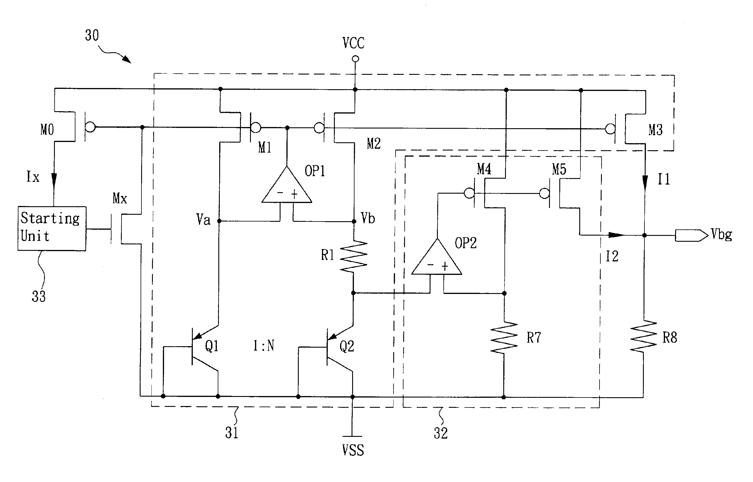
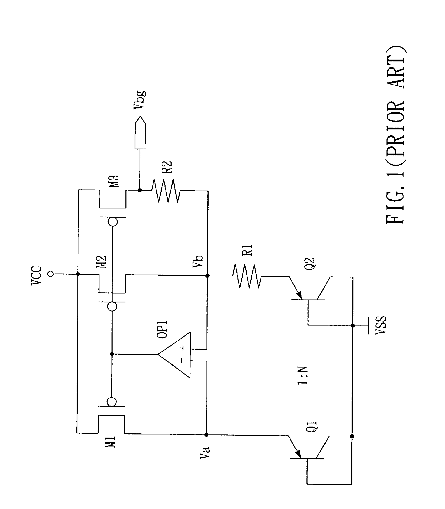
[0025]FIG. 3 is showing the diagram of an embodiment of the fast start-up low-voltage bandgap voltage reference circuit of the present invention. As shown in FIG. 3, the fast start-up low-voltage bandgap voltage reference circuit 30 of the present invention comprises two current generators, namely the first current generator 31 and the second current generator 32. The first current generator 31 is substantially the same with the conventional bandgap voltage reference circuit shown in FIG. 1. The first current generator 31 shown in FIG. 3 is used to generate a first reference current I1 with positive temperature coefficient, while the second current generator 32 is used to generate a second reference current 12 with negative temperature coefficient.

[0026]As shown in FIG. 3, the output end of the first amplifier OP1 is connected to both gat...


PUM


Abstract

A fast start-up low-voltage bandgap voltage reference circuit is disclosed. The bandgap voltage reference circuit includes: a first current generator, which is implemented by a self-bias unit and a current mirror for generating a first reference current with positive temperature coefficient; a second current generator, which is connected to a point with negative temperature coefficient in the first current generator to generate a second reference current with negative temperature coefficient; and a resistor for converting the first reference current and the second reference current into a low-voltage bandgap voltage independent of temperature. Because the bandgap voltage reference circuit of the invention uses the resistor to convert the first reference current and the second reference current into voltage, the circuit can provide low-voltage bandgap voltage.

Description

BACKGROUND OF THE INVENTION[0001]1. Field of the Invention[0002]The present invention generally relates to a bandgap voltage reference circuit, more particularly, to a fast start-up low-voltage bandgap voltage reference circuit.[0003]2. Description of the Prior Art[0004]In general, reference voltage can be generated by voltage-dividing of resistors or by the self-bias of a transistor. However, such reference voltage is not independent of working voltage and temperature, as well as the variation in the manufacturing. In order to solve the problems, a bandgap voltage reference circuit is provided.[0005]The principle of the bandgap voltage reference circuit is to implement components having characteristics of positive temperature coefficient and negative temperature coefficient respectively. And then add the voltages or the currents of these components in a predetermined proper proportion to generate a value independent of temperature, and such value can be output as a reference.[0006]...

Claims


Application Information

Patent Timeline
Patent Type & Authority Patents(United States)
IPC IPC(8): G05F3/08G05F3/30
CPCG05F3/30
Inventor KANG, TZUNG-HUNGLEE, CHAO-CHENG
Owner REALTEK SEMICON CORP
Why Eureka
Try Eureka