Touch control apparatus and touch control method that can be applied to electronic instrument

a technology of electronic instruments and control apparatus, applied in the direction of instruments, coding, pulse techniques, etc., can solve the problems of many manual operations, inability and long time-consuming to achieve the desired touch curve

Inactive Publication Date: 2005-06-14
KAWAI MUSICAL INSTR MFG CO
View PDF13 Cites 15 Cited by
  • Summary
  • Abstract
  • Description
  • Claims
  • Application Information

AI Technical Summary

Benefits of technology

[0016]The present invention is accomplished in view of the above mentioned problems. Therefore, an object of the present invention is to provide a touch control

Problems solved by technology

This results in a problem that only the conventional function of selecting the touch curve can not correspond to a wider age group.
However, in the touch response apparatus according to the first prior art, many manual operations are required to prepare the touch curve.
Thus, it takes a long time to obtain the desirable touch curve.
This results in a problem that it is difficult to prepare the touch curve for a beginner.
Thus, it takes a long time to prepare the touch curves.
Also, the above-mentioned Japanese Patent No.2896948 does

Method used


Image

  • Touch control apparatus and touch control method that can be applied to electronic instrument
  • Touch control apparatus and touch control method that can be applied to electronic instrument
  • Touch control apparatus and touch control method that can be applied to electronic instrument

Examples


first embodiment

(First Embodiment)

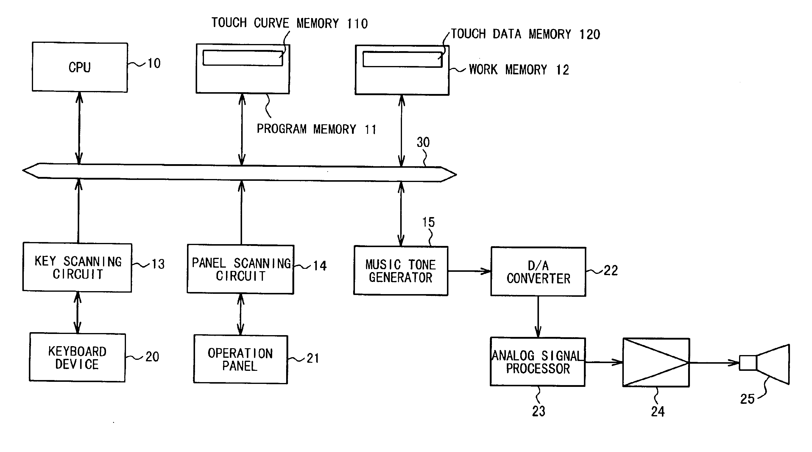
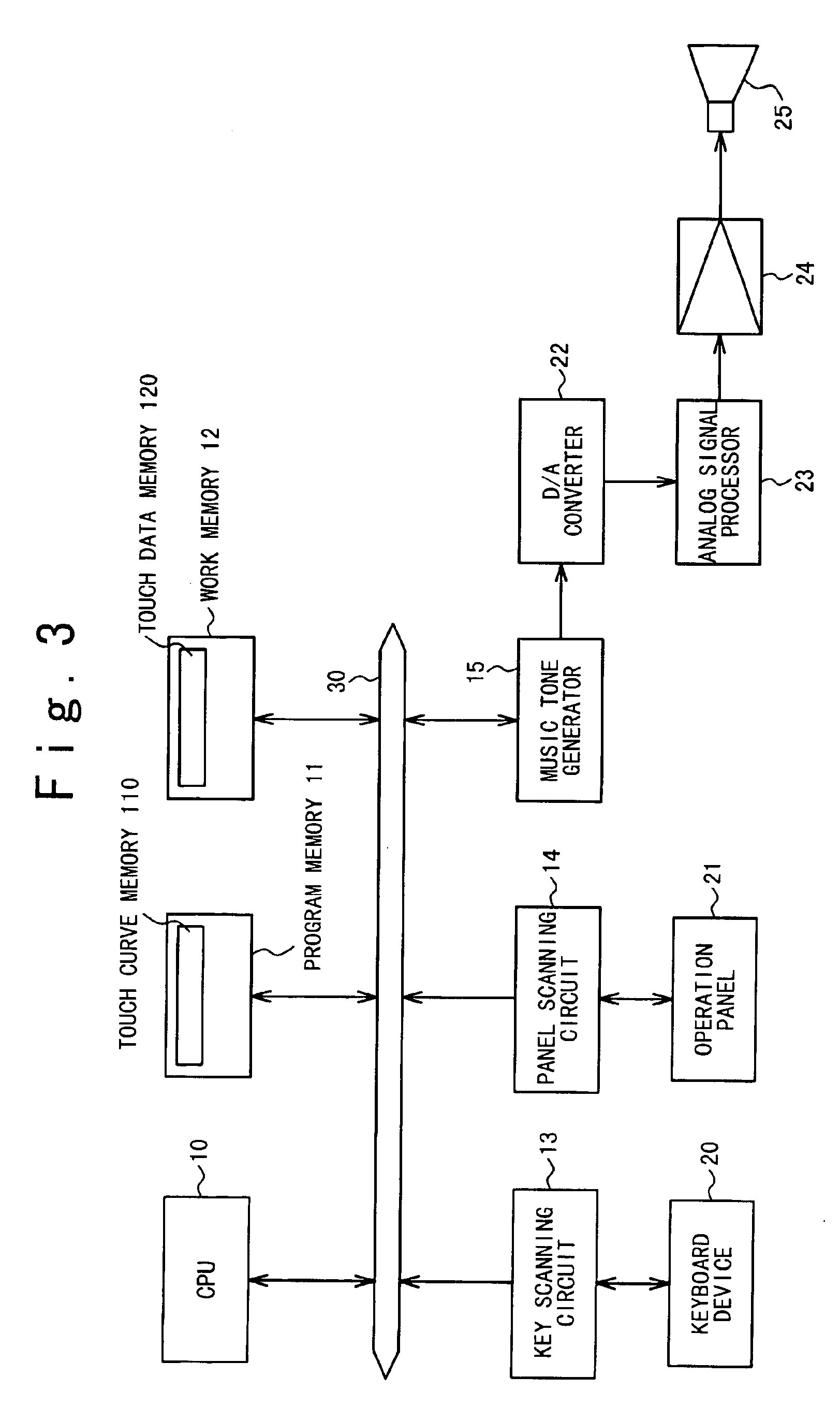
[0049]FIG. 3 is a block diagram showing the configuration of an electronic instrument to which a touch control apparatus according to an embodiment of the present invention is applied. This electronic instrument is composed of a central processing unit (CPU) 10, a program memory 11, a work memory 12, a key scanning circuit 13, a panel scanning circuit 14 and a music tone generator 15 which are connected through a system bus 30 to each other. The system bus 30 sends and receives an address signal, a data signal or a control signal or the like.

[0050]The CPU 10 controls the whole electronic instrument, in accordance with a control program stored in the program memory 11. The content of the control by the CPU 10 will be described later with reference to flowcharts.

[0051]The program memory 11 is composed of, for example, a read only memory (ROM). This program memory 11 stores therein various fixed data used by the CPU 10, in addition to the control program. Also, this p...

second embodiment

(Second Embodiment)

[0085]A touch control apparatus according to a second embodiment of the present invention has a correction curve that can be adjusted by a user, in addition to a keyboard curve. A series of controls in which the correction curve is used to correct the keyboard curve and accordingly obtain a velocity value to be used for producing a tone is referred to as UCC (User Curve Control), hereafter.

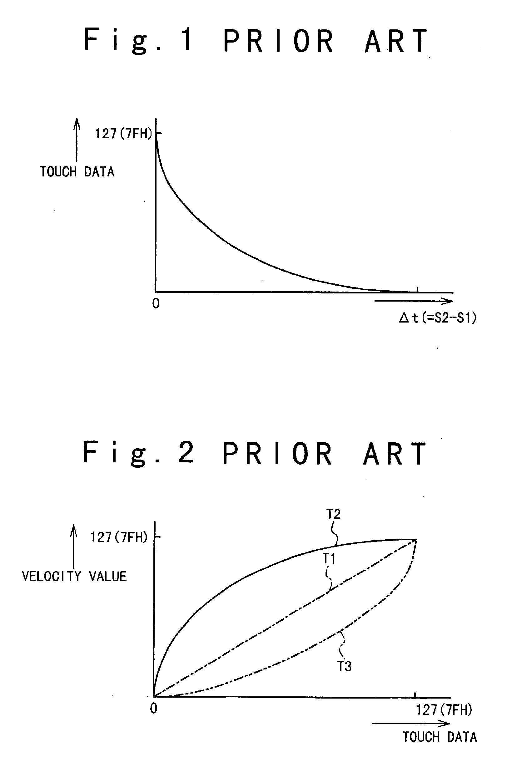
[0086]FIG. 13 shows an example of the keyboard curve. Here, the keyboard curve is defined as follows. The key push speed Δt (refer to FIG. 1) outputted from a touch sensor contained in a keyboard device is different between a white key and a black key. Also, the key push speed Δt is varied depending on the kind of the keyboard device. When the key is pushed under the predetermined force, a touch data is corrected such that a predetermined value is outputted irrespectively of the difference between the white key and the black key and the kind of the keyboard device. The keyboard ...

third embodiment

(Third Embodiment)

[0122]In an electronic instrument to which a touch control apparatus according to a third embodiment of the present invention is applied, when a user hits the key, its hitting force is displayed on a display.

[0123]The configuration of this electronic instrument is identical to that of the electronic instrument to which the touch control apparatus according to the first embodiment shown in FIG. 3 is applied, except the configuration of the operation panel. Thus, a configuration and an operation is mainly described below.

[0124]An operation panel 21 of the electronic instrument includes a display 43 shown in FIG. 23, in addition to the above-mentioned LCD. This display 43 is composed of a plurality of LEDs. When a key on the keyboard device 20 is pushed, any of the plurality of LEDs is turned on in accordance with a touch data at that time.

[0125]Next, an operation of this electronic instrument will be described below. The contents of a main process and a panel event p...


PUM


Abstract

A touch curve memory 110 stores therein a touch curve formed by velocity values corresponding to touch data generated by a keyboard device 20. A correction coefficient generator 10 generates a correction coefficient composed of a ratio of one of the velocity values stored in the touch curve memory corresponding to one of the touch data generated by the keyboard device, in a maximum touch memory mode switched by a mode switch 21 (SW1), to a maximum value of the velocity values in the touch curve memory. A corrector 10 multiplies the correction coefficient generated by the correction coefficient generator by the respective velocity values stored in the touch curve memory, and then generates a touch curve formed by new velocity values. Accordingly, it is possible to provide a touch control apparatus and a touch control method which can obtain a touch curve, from which a touch response suitable for a user can be obtained, easily and in a short time.

Description

BACKGROUND OF THE INVENTION[0001]1. Field of the Invention[0002]The present invention relates to a touch control apparatus and a touch control method that can be applied to an electronic instrument. More particularly, the present invention relates to a technique for obtaining a touch response optimal for a keying power of a user.[0003]2. Description of the Related Art[0004]Typically, a characteristic of the touch response in an electronic keyboard instrument, such as an electronic piano, is determined in accordance with a touch curve. The keyboard instrument, which can control the touch response, has in each key a first key switch S1 to be turned on by a first push depth and a second key switch S2 to be turned on by a second push depth deeper than the first push depth. Signals indicating an on state and an off state of the first key switch S1 and the second key switch S2 are supplied to a touch sensor. The touch sensor measures a time until the signal indicating that the second key ...

Claims


Application Information

Patent Timeline
IPC IPC(8): G10H1/057G10H1/02
CPCG10H1/0575G10H1/02
Inventor ISHIDA, TADAYUKITANAKA, HIDEYUKIYAMAUCHI, KIKURO
Owner KAWAI MUSICAL INSTR MFG CO
Why Eureka
Try Eureka