
Network communications link

a network communication and link technology, applied in the field of communication networks, can solve the problems of low speed of wireless communication links, inconvenient connection of single computers or internet-enabled televisions to communication lines in homes or small offices, and high cost of modems both to purchase and us

Inactive Publication Date: 2005-06-14
INFRA COM
View PDF32 Cites 32 Cited by
  • Summary
  • Abstract
  • Description
  • Claims
  • Application Information

AI Technical Summary

Benefits of technology

[0011]It is still a further object of some aspects of the present invention to provide devices and systems for wireless telephone communications within a home or office. It is an additional object of some aspects of the present invention to provide wireless communication devices and systems that do not require a clear line of sight between the communication devices.

Problems solved by technology

For example, cellular modems may be used without the need for telephone wires, but such modems are expensive both to purchase and to use.
Existing IR wireless communications links generally operate at low speed, however, and carry only limited digital signals, rather than video and voice information.
Generally speaking, they are not suited for connection of a single computer or Internet-enabled television to a communication line in a home or small office.
Elcom Technologies, of Canada, has recently announced the “EZONLINE” modem, which operates by modulating AC power lines, but this new technology is not yet widely used or available, nor is it really wireless, since it simply uses the AC lines in place of the telephone wires.

Method used


Image

  • Network communications link
  • Network communications link
  • Network communications link

Examples


Embodiment Construction

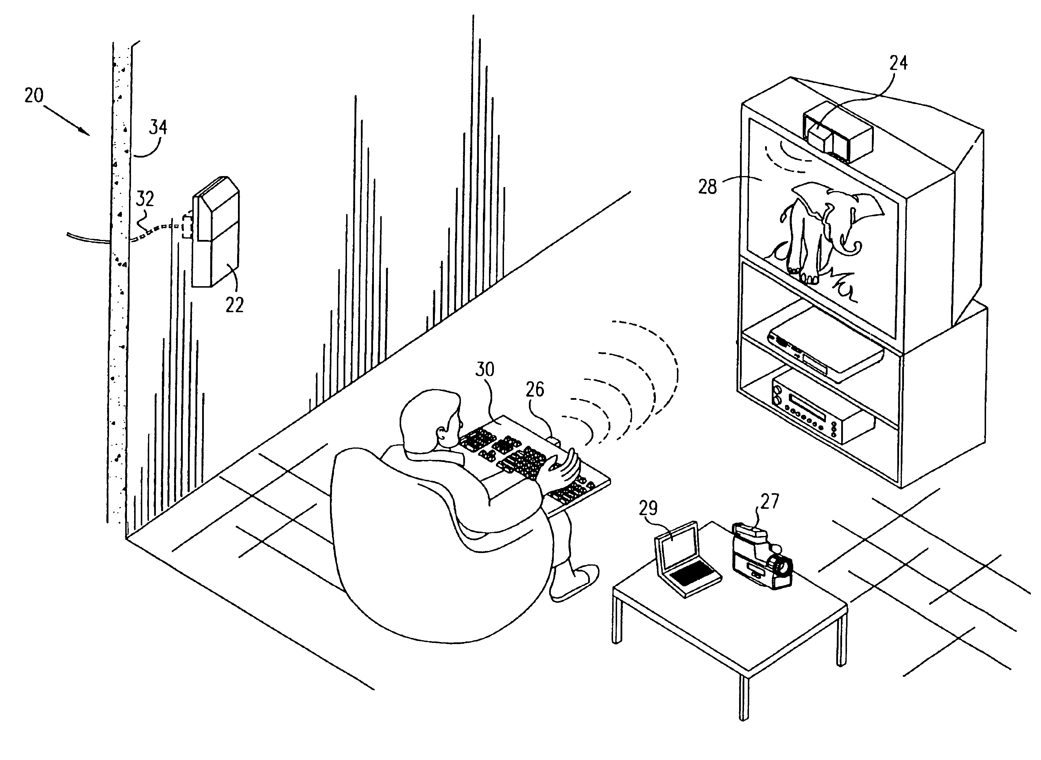
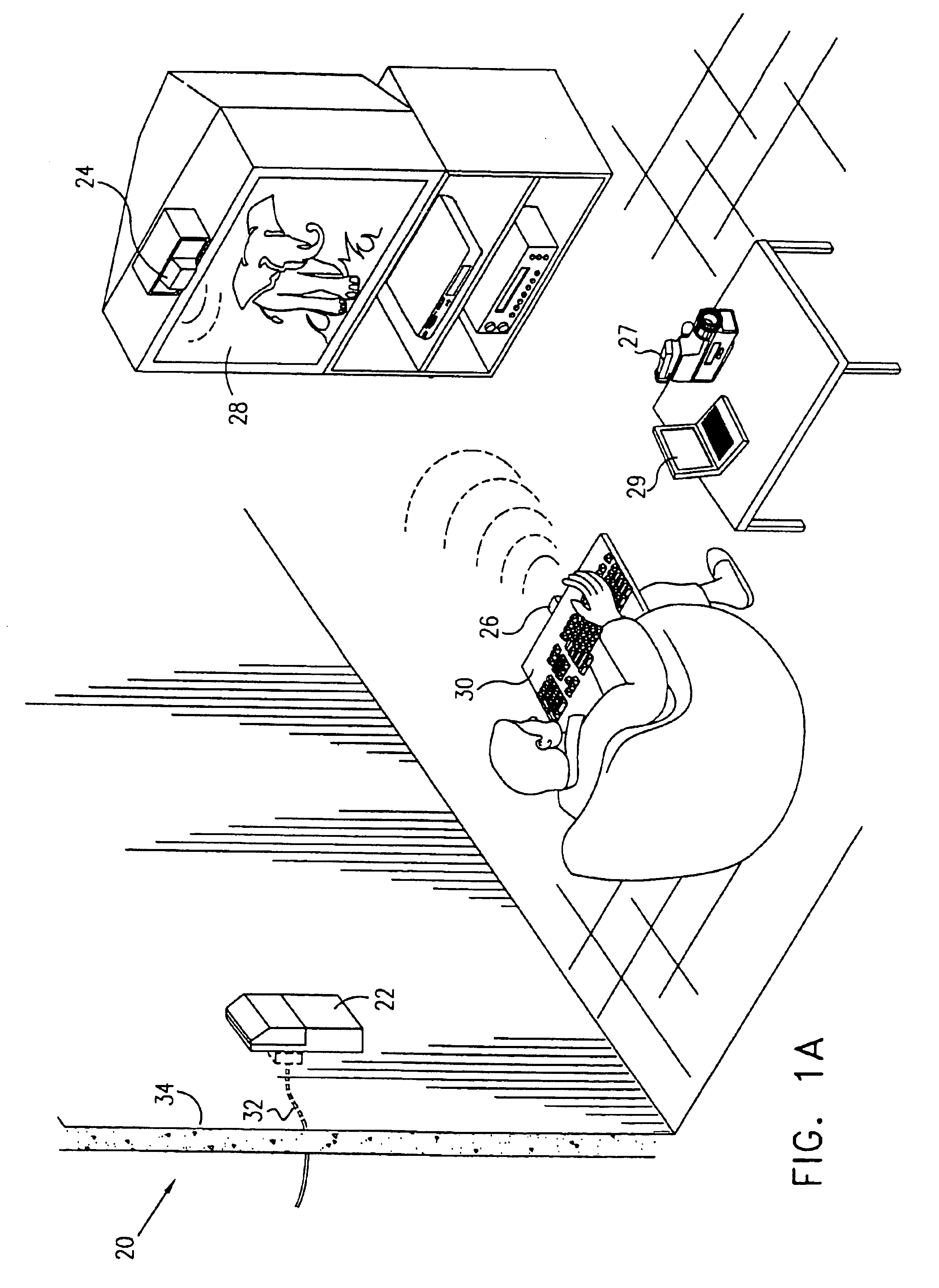
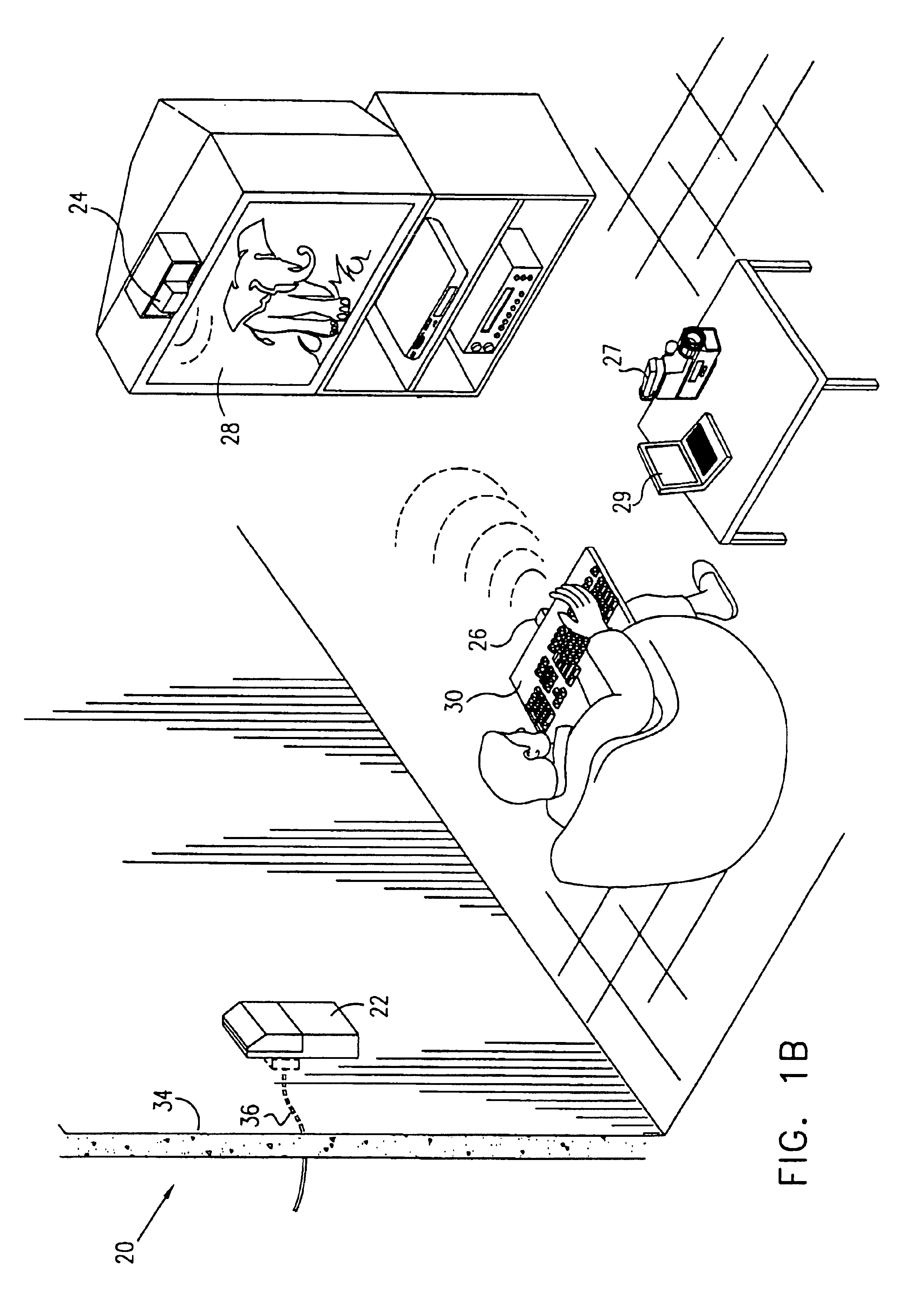
[0069]Reference is now made to FIGS. 1A, 1B, and 1C, which are illustrations of a network communications link 20, in accordance with respective preferred embodiments of the present invention. Link 20 comprises a base unit 22, which transmits and receives modulated diffuse IR radiation to / from remote units 24 and 26. Remote unit 24 is preferably located on, or built into a web-enabled television 28. Remote unit 26 is preferably located in or fixed to a keyboard 30.

[0070]Alternatively or additionally, base unit 22 may transmit and receive radiation to / from remote units located on or built into a digital camera 27 or a personal data assistant 29.

[0071]Link 20 enables a user of television 28 to communicate over the Internet or other computer network through base unit 22. The term “web-enabled” as used herein means that the television includes circuitry for computer network communications, using the television screen as a computer monitor.

[0072]It is noted that although in FIGS. 1A, 1B, ...


PUM


Abstract

A wireless communications link between a communication line connector and at least one audio-visual device is provided. The communications link preferably includes a communication line side unit, including: (a) a communication line side connector for engagement with the communication line connector for bidirectional audio-visual data communication, providing communication between a communication line and the at least one audio-visual device, (b) a communication line side infrared transmitter adapted to transmit diffuse infrared radiation corresponding to the data communication, and (c) a communication line side infrared receiver adapted to receive diffuse infrared radiation corresponding to the data communication. The communications link preferably also includes an audio-visual device side unit, including: (a) an audio-visual device side connector for engagement with the at least one audio-visual device for bidirectional signal communication therewith via a universal serial bus (USB), (b) an audio-visual device side infrared transmitter adapted to transmit diffuse infrared radiation to the communication line side infrared receiver, and (c) an audio-visual device side infrared receiver adapted to receive diffuse infrared radiation from the communication line side infrared transmitter.

Description

CROSS-REFERENCE TO RELATED APPLICATIONS[0001]This application is a continuation-in-part of U.S. patent application Ser. No. 08 / 992,934, entitled “Network communications link,” filed Dec. 17, 1997, now U.S. Pat. No. 6,256,296, which is a continuation-in-part of U.S. patent application Ser. No. 09 / 444,422, filed Nov. 19, 1999, now abandoned, entitled “Network Communications Link”. Both of these applications are assigned to the assignee of the present patent application and are incorporated herein by reference.FIELD OF THE INVENTION[0002]The present invention relates generally to communication networks, and specifically to wireless communication networks based on infrared radiation.BACKGROUND OF THE INVENTION[0003]The Internet is the world's fastest developing mass media channel. Not only are increasing numbers of home computer users using the Internet, but most major television manufacturers are also developing or introducing Internet-connectable television sets. Since Internet connec...

Claims


Application Information

Patent Timeline
IPC IPC(8): H04B1/20H04B10/10
CPCH04B1/202H04B10/1143H04B10/114
Inventor RUZIAK, YARON
Owner INFRA COM
Learn More