Coated optical fiber, optical fiber tape core using it and optical fiber unit

Inactive Publication Date: 2005-06-14
SUMITOMO ELECTRIC IND LTD
View PDF12 Cites 8 Cited by
  • Summary
  • Abstract
  • Description
  • Claims
  • Application Information

AI Technical Summary

Benefits of technology

[0006]Therefore, it is an object of the present invention to provide a coated optical fiber which can sufficiently prevent transmission characteristics from deteriorating in a low temperature environment, and a coated optical fiber ribbon and optical fiber unit using the same.
[0007]The inventors conducted diligent studies in order to solve the above-mentioned problem and, as a result, have found that a coated optical fiber formed by coating a silica type glass optical fiber with n layers of UV-curable resin can fully prevent transmission characteristics from deteriorating at a low temperature when the sum of contraction stress indices FI defined according to the Young's modulus at −40° C., cross-sectional area, effective linear expansion coefficient, and the like of each layer becomes a predetermined value or lower, thereby accomplishing the present invention.
[0010]They can fully prevent transmission loss from deteriorating at a low temperature, since they contain a coated optical fiber which can fully prevent transmission loss from deteriorating at a low temperature.

Problems solved by technology

As a result, it was found that there were cases where the conventional coated optical fiber disclosed in the above-mentioned publication deteriorated its transmission characteristics in a low temperature environment of 0 to 5° C. and, in particular, there were cases where it became hard to be put into practical use for optical communications in conformity to the wavelength division multiplexing (WDM) scheme in a low temperature environment.

Method used


Image

  • Coated optical fiber, optical fiber tape core using it and optical fiber unit
  • Coated optical fiber, optical fiber tape core using it and optical fiber unit
  • Coated optical fiber, optical fiber tape core using it and optical fiber unit

Examples


examples 1 to 8

[0063](Making of Coated Optical Fiber)

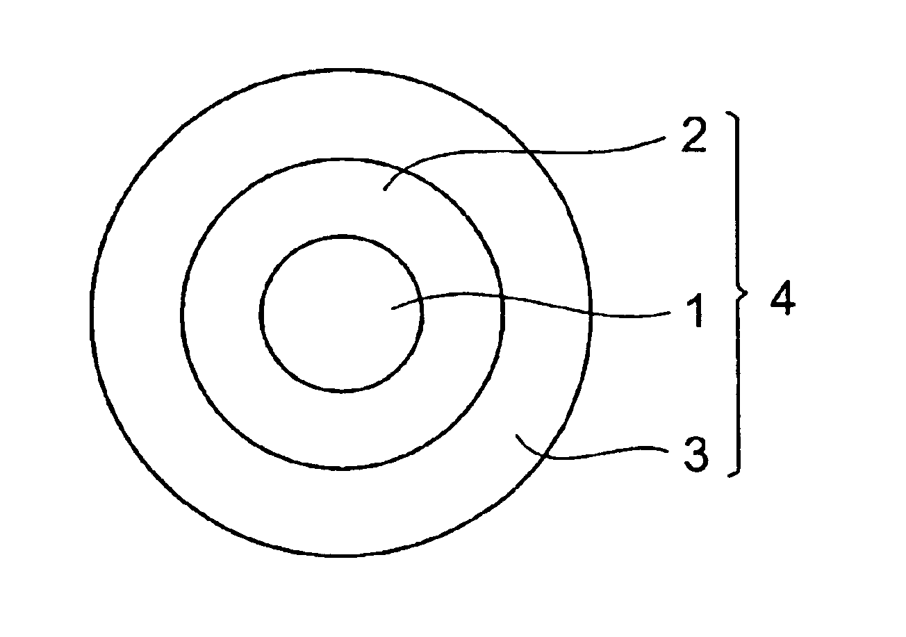
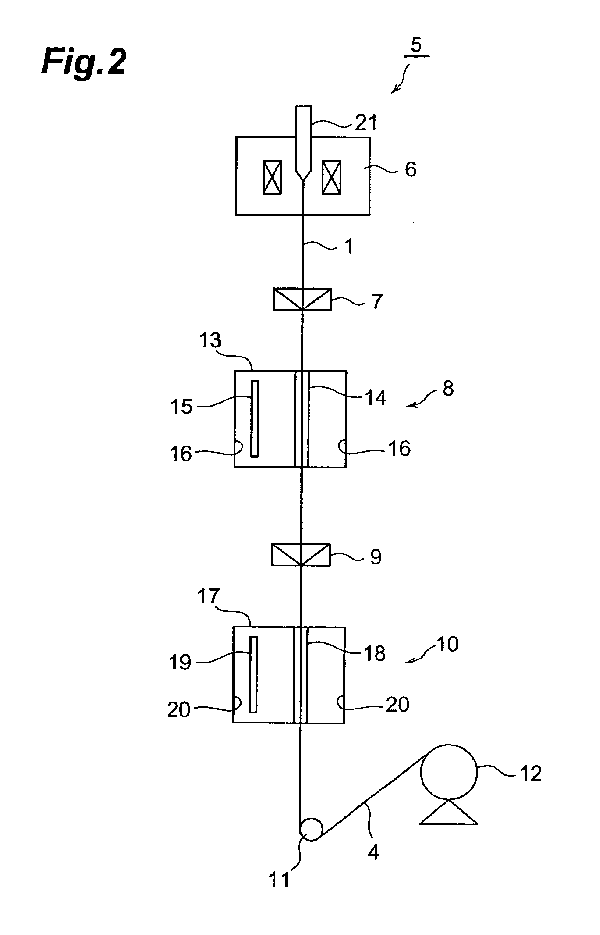
[0064]Using the drawing apparatus 5 shown in FIG. 2, the coated optical fiber 4 was prepared as follows: First, the front end of the optical fiber preform 1 was inserted in the drawing furnace 6 heated at 1950° C., so as to be drawn upon melting, thus yielding a dispersion-shifted optical fiber 1 having a double core type refractive index profile, an effective core area of 85 μm2, and an outer diameter of 125 μm. Thus obtained product was passed through the die 7 containing the first layer resin composition, so as to be coated with the first layer resin composition, which was then irradiated with UV rays by the first UV irradiating unit 8, so as to be cured. Thus, the first UV-curable resin layer was formed on the optical fiber 1. As the first layer resin composition, those listed in Table 1 were used. As the UV lamp, a metal halide lamp was used.

[0065]

TABLE 1AverageEffectivelinearlinearexpansionexpansionContractioncoefficientcoefficientstressYo...

examples 9 and 10

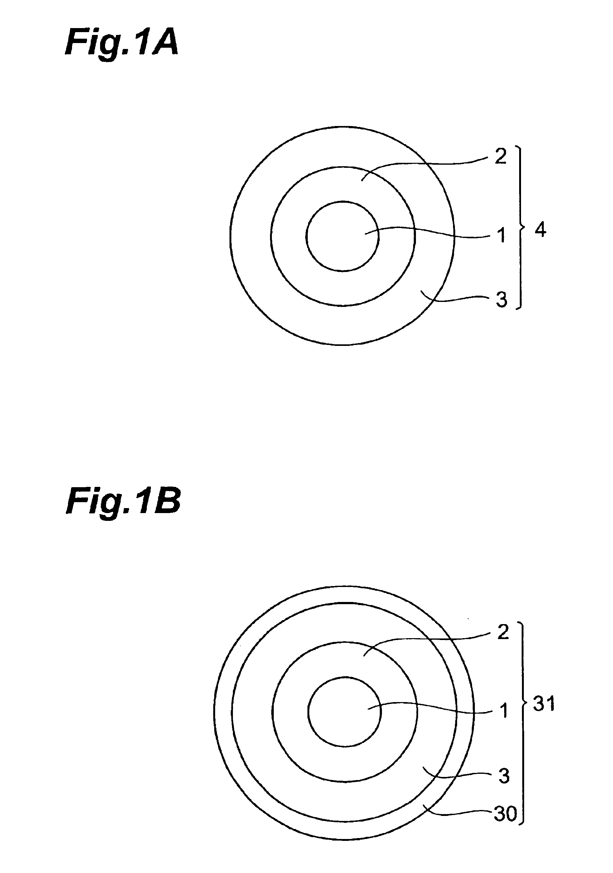
[0098]A coated optical fiber was made in the same manner as Example 1, 7, or 8, except that the third UV-curable resin layer obtained by the resin compositions listed in Table 5 was further provided on the second UV-curable resin layer, and that the outer diameters of the first to third UV-curable resin layers were set to their respective values shown in Table 5.

[0099]

TABLE 5AverageEffectivelinearlinearexpansionexpansionContractioncoefficientcoefficientstressYoung'sαaHardeningLinearαeffindexResinInnerOutermodulus(150˜shrinkageshrinkage(150˜Totalcompo-diameterdiameterCross-sectional23° C.−40° C.−40° C.)ratioratio−40° C.)FIFIExampleLayersition[mm][mm]area [mm2][MPa][MPa][10−5 / ° C.]s[−]s′[−][10−5 / ° C.][N][N]Example1Rs2-10.1250.2000.01910.7606100.0310.01046650.151.9 92Rh20.2000.2350.0120100020002000.0550.01872981.363Rh40.2350.2450.0038120030001000.0500.01701890.41Example1Rs2-10.1250.2100.02240.7606100.0310.01046650.171.6102Rh20.2100.2350.0087100020002000.0550.01872980.993Rh40.2350.2450....

example 11

[0104]Coated optical fibers were made in the same manner as Examples 1 to 6 except that Rs1 was used in place of Rs2-1.

[0105]In these coated optical fibers, the cross-sectional area, Young's modulus, average linear expansion coefficient αa, linear shrinkage ratio, hardening shrinkage ratio, and effective linear expansion coefficient αeff in each of the first and second UV-curable resin layers were calculated as in Examples 1 to 6. Then, the respective contraction stress indices FI of the individual layers, and their sum were determined. Table 5 shows the results.

[0106]Further, thus obtained coated optical fibers were studied in terms of low-temperature transmission and microbending, and were subjected to a high-tension screening test. Table 7 shows the results.


PUM

PropertyMeasurementUnit
Temperatureaaaaaaaaaa
Lengthaaaaaaaaaa

Abstract

The present invention provides a coated optical fiber in which a silica type optical fiber is coated with n layers (n being an integer of 2 or greater) of UV-curable resin, wherein the sum of respective contraction stress indices FI defined in the n layers of UV-curable resin by the following expression: FI [N]=(Young's modulus [MPa] of the UV-curable resin layer at −40° C.)×(cross-sectional area [mm2] of the UV-curable resin layer)×(effective linear expansion coefficient [10−6 / ° C.] / 106)×(temperature difference 190[° C.]) is 3 [N] or less. The present invention can sufficiently prevent transmission characteristics from deteriorating in a low temperature environment.

Description

TECHNICAL FIELD[0001]The present invention relates to a coated optical fiber, and a coated optical fiber ribbon and optical fiber unit using the same.BACKGROUND ART[0002]Coated optical fibers used in optical communications are generally made by coating optical fibers with a resin, whereas the resin usually constitutes two layers consisting of a primary coating layer as the inner layer and a secondary coating layer as the outer layer.[0003]An example of such coated optical fibers is disclosed in Japanese Patent Application Laid-Open No. HEI 8-248250. The coated optical fiber disclosed in this publication uses a primary coating layer having a Young's modulus of 1.0 to 3.0 MPa and a glass transition point of −10° C. or lower, and a secondary coating layer having a Young's modulus of at least 400 MPa.DISCLOSURE OF THE INVENTION[0004]Meanwhile, coated optical fibers are used in submarine optical communications as well. Therefore, they have been desired to realize favorable transmission c...

Claims


Application Information

Patent Timeline
IPC IPC(8): C03C25/10G02B6/44C03C25/32C03C25/50
CPCC03C25/1065C08G18/672C09D133/14C09D175/16G02B6/4403C08G18/48G02B6/44
Inventor SUZUKI, ATSUSHIHATTORI, TOMOYUKIHOSOYA, TOSHIFUMI
Owner SUMITOMO ELECTRIC IND LTD
Why Eureka
Try Eureka