Mobile communication base station equipment

a mobile communication and equipment technology, applied in the field of mobile communication base station equipment, can solve the problems of increasing the scale of equipment, increasing the number of antennas, and reducing the quantity of interference caused by radiated power, so as to achieve the effect of reducing the number of interferences

Inactive Publication Date: 2005-06-14
NTT DOCOMO INC
View PDF11 Cites 116 Cited by
  • Summary
  • Abstract
  • Description
  • Claims
  • Application Information

AI Technical Summary

Benefits of technology

[0010]It is another object of the invention to provide a mobile communication base station equipment which allows the quantity of interferences caused by radiated power to be reduced as compared with the prior art.

Problems solved by technology

However, this practice requires a plurality of transmitters / receivers for each channel for both the transmission and the reception, disadvantageously increasing the scale of the equipment.
When the technique is applied to the mobile communication, which represents a multi-path environment, a difficulty is encountered in establishing an accurate beam switching because of a variation in the signal strength which occurs independently on each antenna branch.
A high resolution signal processing technique such as MUSIC is known in the art to estimate the arriving direction of a radiowave (DOA; Direction of Arrival), but requires a complex treatment including the calculation of a correlation matrix, resulting in a tremendous length of time as the number of antennas increases.
The treatment of this technique is even more complicated when plural antenna having different directivities are used.
Thus, when commencing a communication with a particular user (mobile station), the base station equipment is radiating radio waves in directions of its service area such as a sector area, for example, other than the direction on which the user is located, and this represents a wasteful power dissipation.
It will thus be seen that the use of antennas which exhibit a common angle directivity response for every frequency channel and time slot is problematic from the standpoints of radio wave environment and power saving.
The proposed technique is excellent when viewed from above standpoints, but presents problems in that an increased area must be provided for installation of antennas and the equipment must be scaled up.
In addition, a complex signal processing system is needed.
As discussed, the arrangement which employs the direction finding of the mobile station and a result of such scan is used in switching a transmit / receive beam suffers from the accuracy of directional finding, the scale of equipment and the quantity of calculations.
It will also be seen that because a wide angle beam antenna is fixedly assigned to every channel in a conventional base station equioment, this means that the equipment dissipates a wasteful radiation power in directions in its service area (such as a sector, for example) other than the direction on which a desired mobile station is located, contributing to increasing the quantity of interferences with other base stations.

Method used


Image

  • Mobile communication base station equipment
  • Mobile communication base station equipment
  • Mobile communication base station equipment

Examples


Embodiment Construction

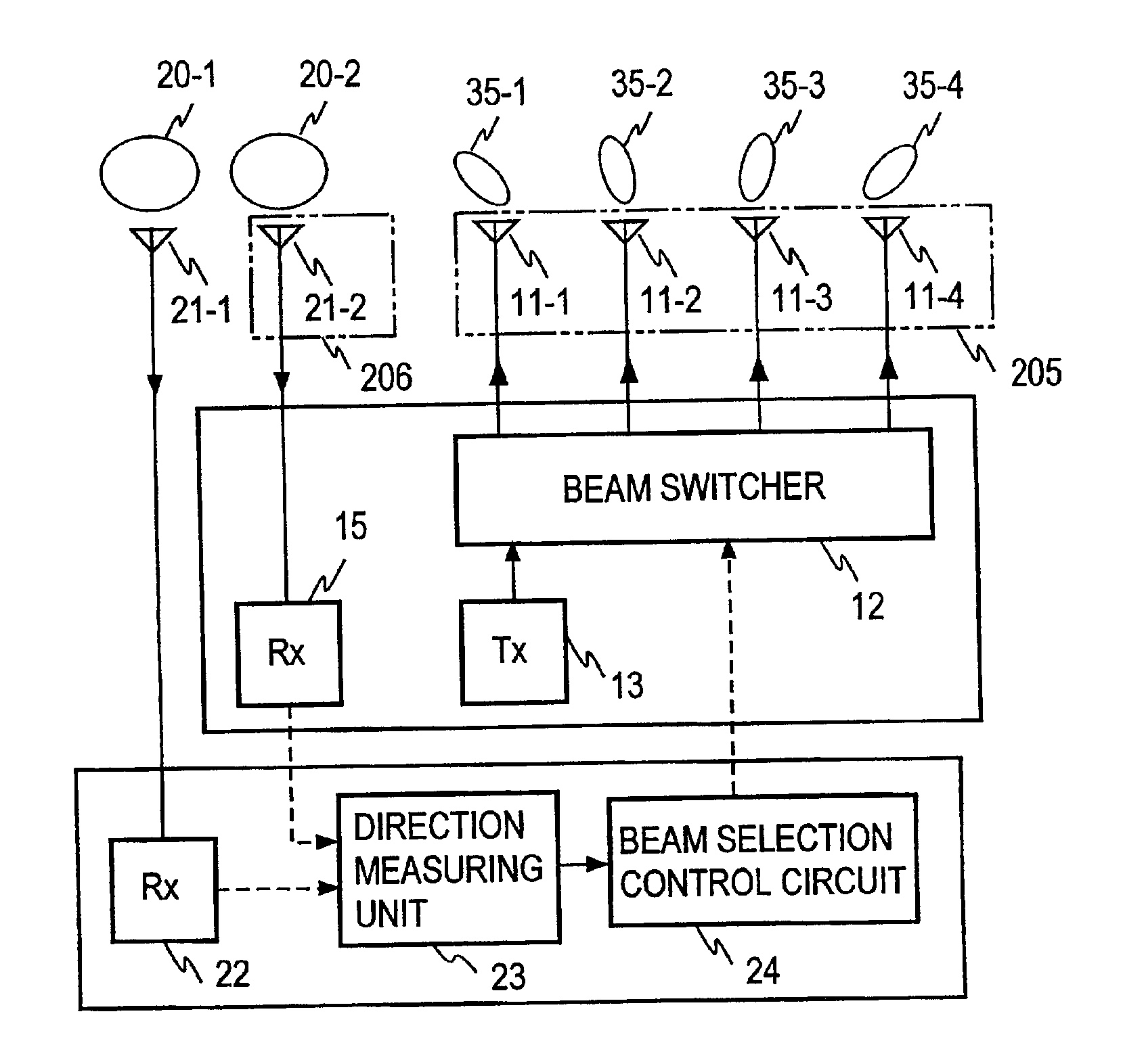
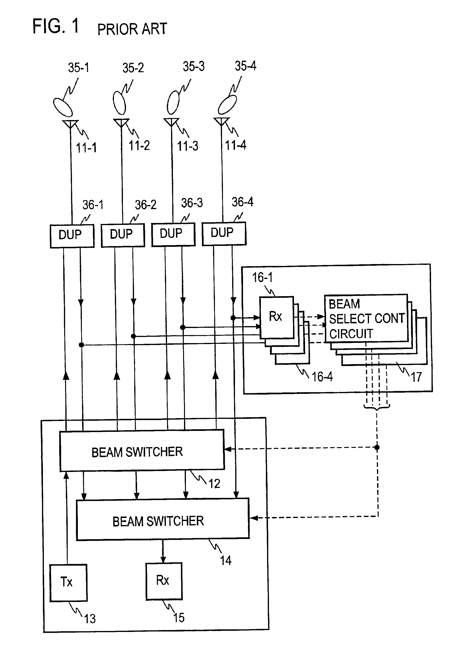
[0049]FIG. 5A shows an embodiment according to the first aspect of the present invention, and corresponding parts to those shown in FIG. 1 are designated by like reference characters as used in FIG. 1, it being understood that throughout the description to follow, a similar convention is followed. In this embodiment, there are provided a pair of antennas 21-1 and 21-2 which exhibit a wide angle directivity response (or wide angle beam). Each of the wide angle beam antennas 21-1 and 21-2 is capable of substantially covering a service area which is collectively covered by narrow angle beam antennas 11-1 to 11-4. It is to be understood that the both antennas 21-1 and 21-2 are located close to each other so as to be within the order of one-half the wavelength (λ) of radio waves involved, and have wide angle beams 20-1 and 20-2 having central axes which are parallel to each other.

[0050]A direction finder receiver 22 is connected to one of the wide angle beam antennas, 21-1, while a commu...


PUM


Abstract

A mobile communication base station determines the oncoming direction of a radio wave with a simple arrangement and transmits a narrow angle beam in this direction. Received signals from a pair of wide angle beam antennae 21-1 and 21-2 having an equal configuration and a common orientation and which are located close to each other are fed to a direction finder receiver 22 and a communication receiver 15. By utilizing the fact that the both received signals have a coincident amplitude, a phase difference between the received signals is detected. The oncoming direction of the received radio wave (or the direction of a mobile station) is determined on the basis of the phase difference. A beam switcher 12 is controlled so as to connect a transmitter 13 to a narrow angle beam antenna (one of 11-1 to 11-4) which is directed in the oncoming direction thus determined.

Description

BACKGROUND OF THE INVENTION[0001]The present invention relates to a base station equipment of a mobile communication system which is intended to enable a communication with a mobile station with a narrow angle directivity (narrow angle beam) antenna in order to reduce the quantity of interferences.[0002]An adaptive array antenna in a conventional mobile communication base station equipment is constructed by providing a plurality of receivers for each communication channel, adjusting an antenna weight to control the direction of a principal beam in the antenna directivity response, extracting an optimal received signal, and employing the antenna weight which is used for the optimal signal in controlling the direction of a principal beam in the directivity response of a transmitting antenna. However, this practice requires a plurality of transmitters / receivers for each channel for both the transmission and the reception, disadvantageously increasing the scale of the equipment.[0003]To...

Claims


Application Information

Patent Timeline
Patent Type & Authority Patents(United States)
IPC IPC(8): H01Q3/26H01Q1/24H01Q3/24H04B7/155
CPCH01Q1/246H01Q3/2605H01Q3/24H04B7/155H04W16/28H04W52/30
Inventor YAMAGUCHI, RYOTERADA, NORIYOSHINOJIMA, TOSHIO
Owner NTT DOCOMO INC
Why Eureka
Try Eureka