Electric hammer

a technology of electric hammer and hammer head, which is applied in the field of electric hammer, can solve the problems that the space for receiving such a dynamic vibration reducer also requires considerable space within the hammer, and achieve the effect of improving construction and vibration reduction performan

Active Publication Date: 2005-06-21
MAKITA CORP
View PDF19 Cites 59 Cited by
  • Summary
  • Abstract
  • Description
  • Claims
  • Application Information

AI Technical Summary

Benefits of technology

[0006]It is, accordingly, an object of the present invention to provide an electric hammer with improved construction, while ensuring the vibration reduction performance.
[0007]According to the present invention, a representative electric hammer may include a hammer bit, a driving motor, a crank mechanism and a counter weight. The crank mechanism drives a striker by converting a rotating output of the driving motor to linear motion in the axial direction of the hammer bit. The counter weight is detachably mounted to the crank mechanism and serves to reduce vibration of the striker.
[0008]According to the representative hammer, because the counter weight is detachably mounted to the crank mechanism, it is possible to switch between the mode in which the counter weight is mounted on the hammer body in order to reduce and alleviate vibration and the mode in which the counter weight is removed from the hammer so that the operation can be performed with the hammer having a lighter weight and slimmer appearance. Thus, utility of the electric hammer can be improved.

Problems solved by technology

Accordingly, the space for receiving such a dynamic vibration reducer also requires considerable spaces within the hammer.

Method used


Image

  • Electric hammer
  • Electric hammer
  • Electric hammer

Examples


Embodiment Construction

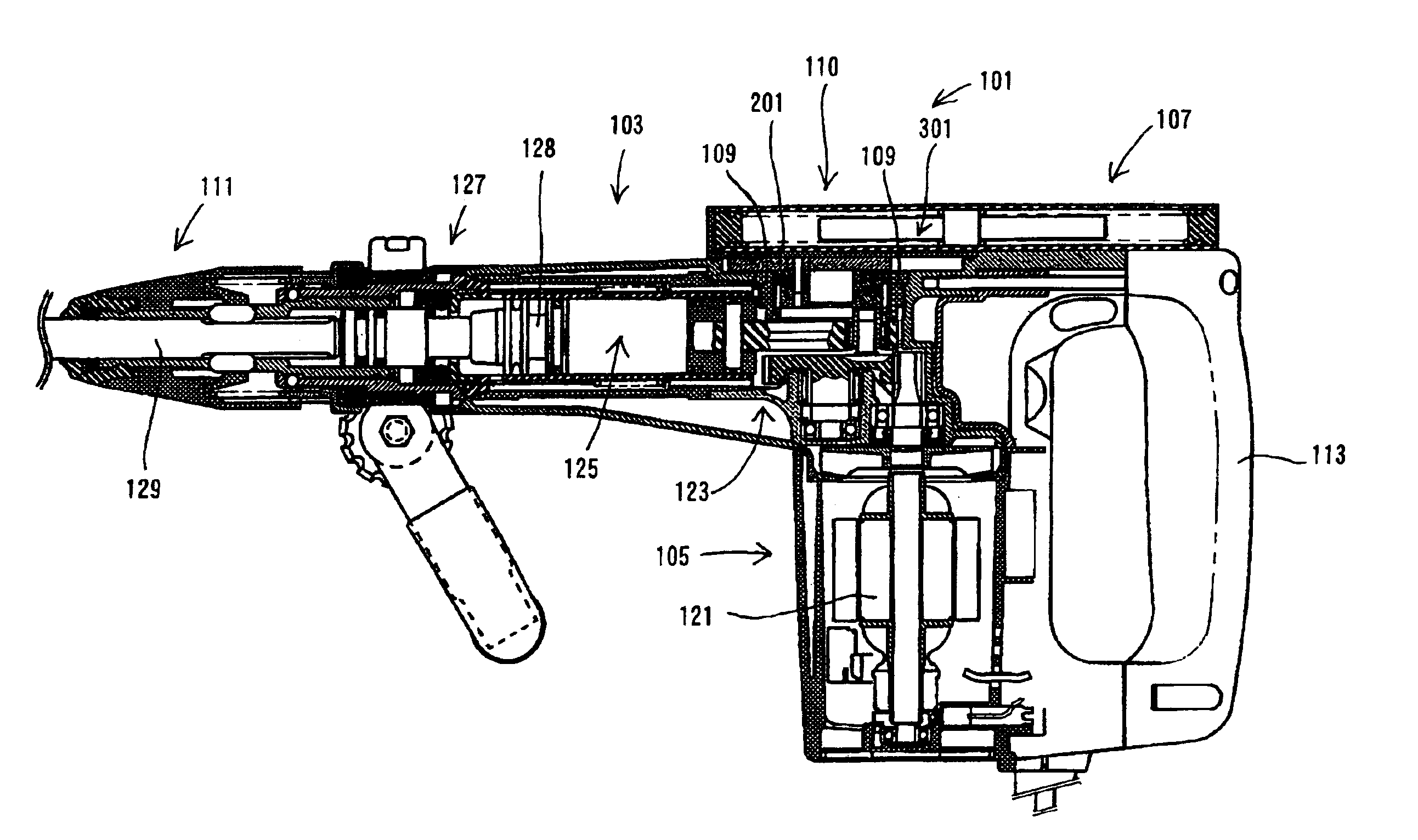
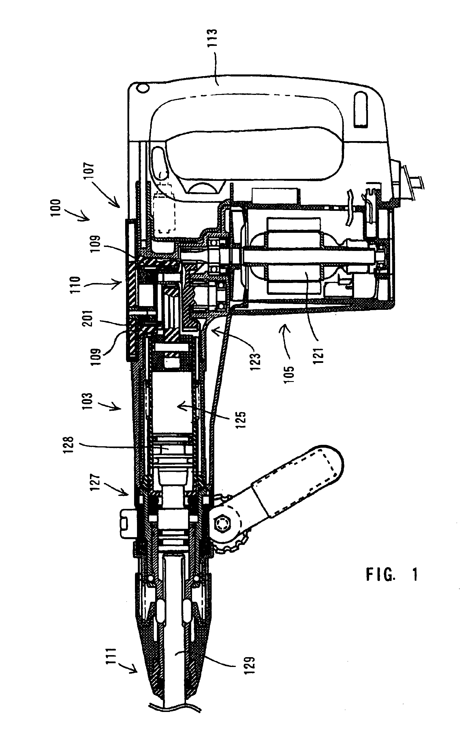
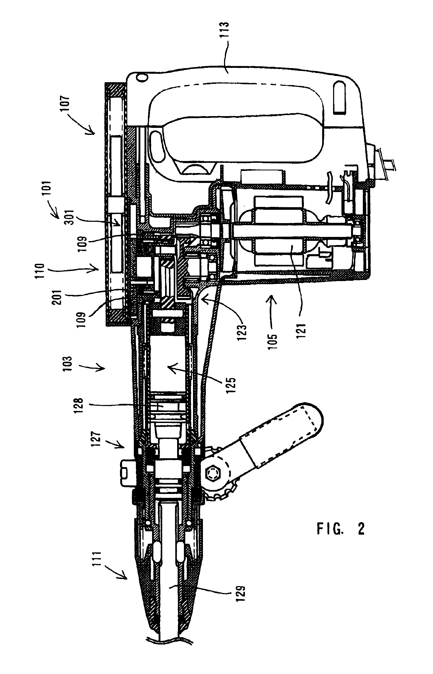
[0015]According to the present invention, a representative electric hammer may include a hammer bit, a driving motor, a crank mechanism and a counter weight. The electric hammer may suitably embrace not only a hammer of the type which performs a hammering function by reciprocating motion of the hammer bit in the axial direction, but a hammer of the drill-hammer type which performs a drilling function by rotation of the hammer bit, as well as the hammering function. The crank mechanism drives a striker by converting a rotating output of the driving motor to linear motion in the axial direction of the hammer bit. The counter weight serves to reduce vibration of the striker. Specifically, the counter weight reciprocates in a direction opposite to the direction of the striker being linearly driven by the crank mechanism. As a result, the kinetic energy (momentum) of the counter weight and the striker is offset against each other, so that the vibration of the entire hammer is effectively...


PUM

PropertyMeasurementUnit
weightaaaaaaaaaa
striking forceaaaaaaaaaa
vibration reduction performanceaaaaaaaaaa

Abstract

It is, accordingly, an object of the present invention to provide an electric hammer with improved construction, while ensuring the vibration reduction performance. According to the present invention, a representative electric hammer may include a hammer bit, a driving motor, a crank mechanism and a counter weight. The crank mechanism drives a striker by converting a rotating output of the driving motor to linear motion in the axial direction of the hammer bit. The counter weight is detachably mounted to the crank mechanism and serves to reduce vibration of the striker. According to the representative hammer, because the counter weight is detachably mounted to the crank mechanism, it is possible to switch between the mode in which the counter weight is mounted on the hammer body in order to reduce and alleviate vibration and the mode in which the counter weight is removed from the hammer so that the operation can be performed with the hammer having a lighter weight and slimmer appearance. Thus, utility of the electric hammer can be improved.

Description

BACKGROUND OF THE INVENTION[0001]1. Field of the Invention[0002]The present invention relates to an electric hammer, and more particularly, to a technique of reducing and alleviating vibration in an electric hammer that drives a hammer bit at a predetermined cycle, such as a hammer and a hammer drill.[0003]2. Description of the Related Art[0004]Japanese unexamined laid-open Utility Model Publication No. 51-6583 discloses a hammer with a vibration reducing device. According to the known hammer, a counter weight is provided on a crank arm mechanism and driven by the crank arm mechanism. The crank arm mechanism is designed to reciprocate the striker that applies a striking force to the hammer bit. The counter weight reciprocates within a gear housing in a direction opposite to the direction of the striker being driven by the crank arm mechanism. Such movement of the counter weight in the opposite direction can effectively reduce and alleviate vibration in the axial direction of the ham...

Claims


Application Information

Patent Timeline
Patent Type & Authority Patents(United States)
IPC IPC(8): B25D17/24B25D17/00B23B45/16B25D11/12
CPCB25D11/125B25D17/24B25D2211/003B25D2250/335B25D2217/0092B25D2250/331B25D2217/0088
Inventor IKUTA, HIROKI
Owner MAKITA CORP
Why Eureka
Try Eureka