

Electromagnetic electroacoustic transducer
- Summary
- Abstract
- Description
- Claims
- Application Information
AI Technical Summary
Benefits of technology
Problems solved by technology
Method used
Image

Examples
Embodiment Construction
[0030]An embodiment of the invention will be described below with reference to the drawings.
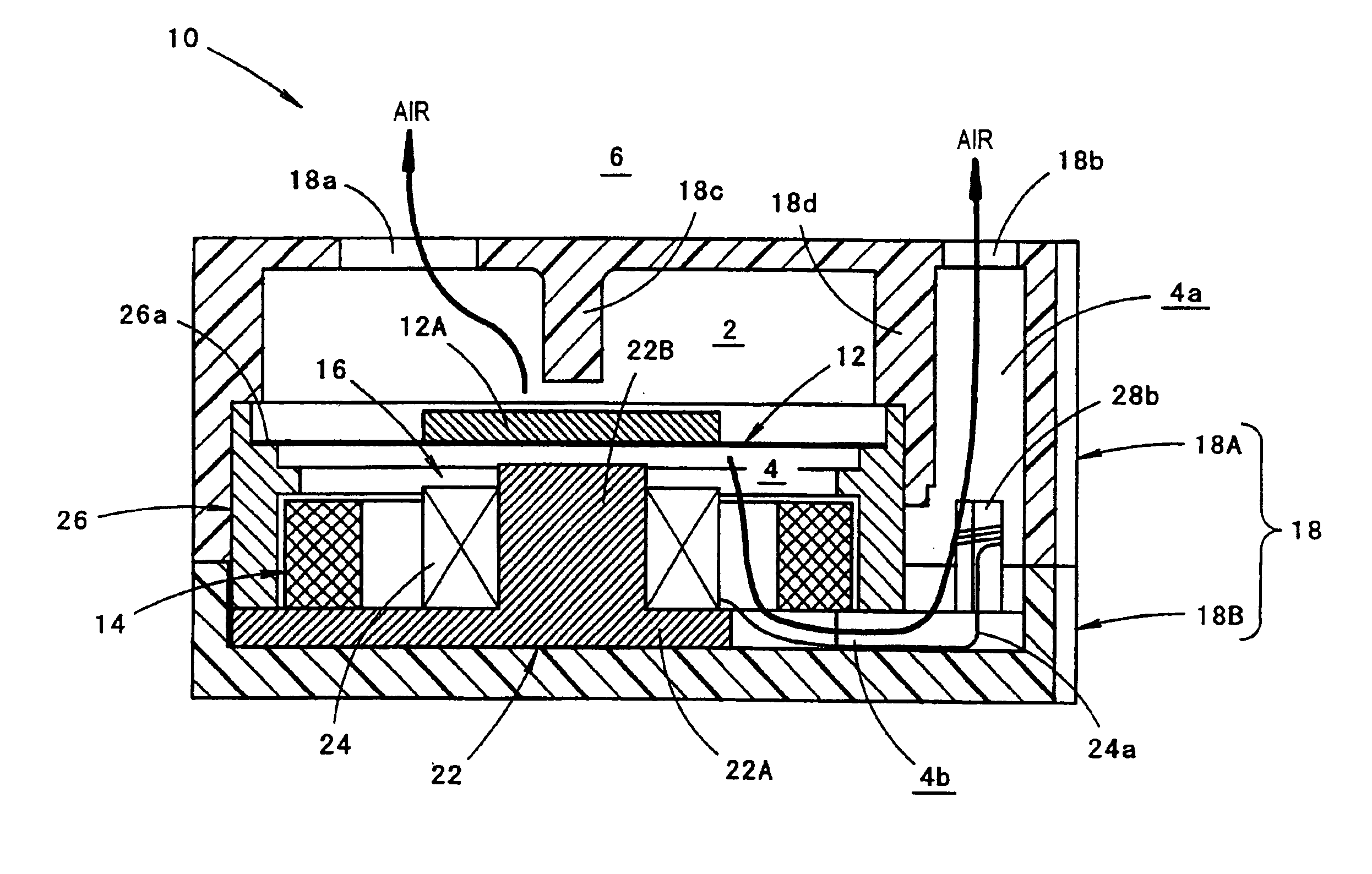
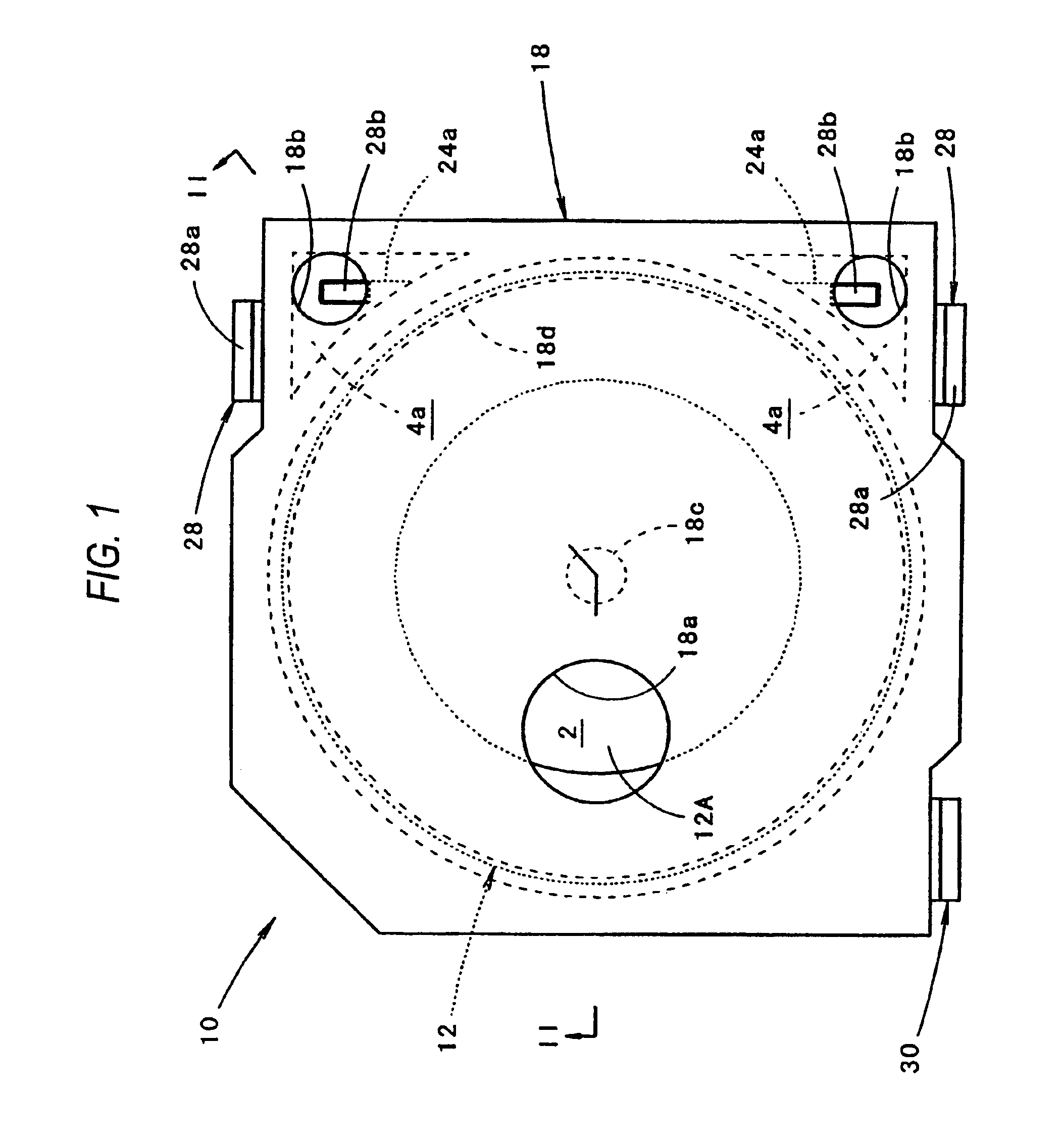
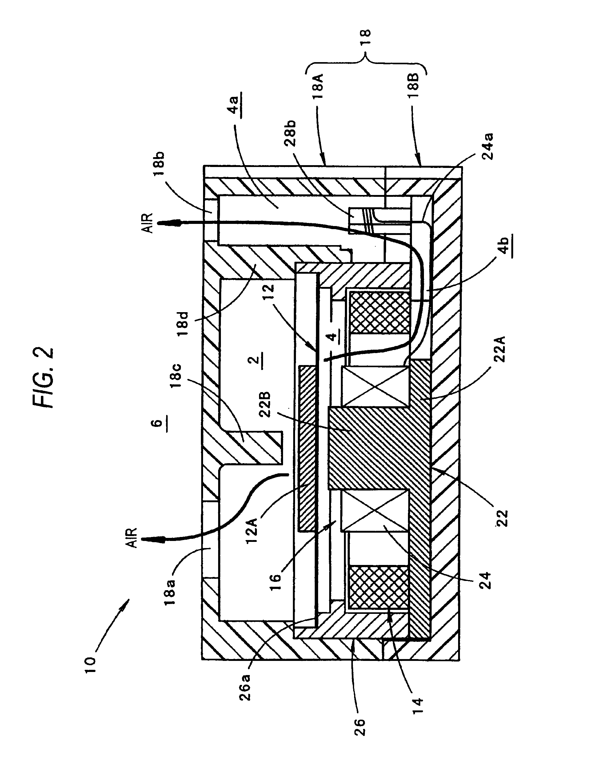
[0031]FIG. 1 is a front view of an electromagnetic electroacoustic transducer 10 according to an embodiment of the invention in the case where the electromagnetic electroacoustic transducer 10 is disposed so as to face upward. FIG. 2 is a sectional view taken along the line II—II in FIG. 1. FIG. 3 is a front view of the electromagnetic electroacoustic transducer 10 in the case where a front casing 18A is removed.
[0032]As shown in FIGS. 1 to 3, the electromagnetic electroacoustic transducer 10 according to this embodiment includes a diaphragm 12 made of a magnetic material, a magnet 14 for generating a magnetostatic field to make the magnetostatic field act on the diaphragm 12, an electromagnetic coil 16 for generating an oscillating magnetic field corresponding to an electric signal to make the oscillating magnetic field act on the diaphragm 12, and a casing 18 in which the diaphragm 12, the ...
PUM
 Abstract
Description
Claims
Application Information