Method for manufacturing magnetic recording medium

a technology of magnetic recording medium and manufacturing method, which is applied in the field of manufacturing a magnetic recording medium, can solve the problems of erroneous recording information, limited accuracy of microprocessing of magnetic heads, and conventional approaches to improve the density of areal cells already reaching their limits, and achieve good recording/reproducing properties

Inactive Publication Date: 2010-06-22
TDK CORPARATION
View PDF27 Cites 1 Cited by
  • Summary
  • Abstract
  • Description
  • Claims
  • Application Information

AI Technical Summary

Benefits of technology

[0018]Since the first filling material is deposited between the recording elements and the detection material, the first filling material can protect the recording elements against etching even when the detection material above the recording elements has been fully removed and the etching has proceeded further.
[0019]When the first filling material is deposited in a thickness greater than the depth of the concave portion, etching may proceed further after the detection material above the recording elements has been fully removed. This may cause the first filling material in the concave portion between the recording elements to be etched in conjunction with the first filling material over the recording elements. Even in this case, only the first filling material is etched both over the recording elements and over the concave portion, thus causing no step heights that would be produced if the recording elements and the filling material were etched in conjunction.
[0020]It is noted that if the deposited first filling material is thinner than the depth of the concave portion, the upper portion of the concave portion is filled with the second filling material. Then, when etching proceeds further after the detection material over the recording elements has been fully removed, the second filling material in the concave portion is etched in conjunction with the first filling material over the recording elements. In this case, the same material or materials that have similar etching rates for dry etching in the flattening step may be selected as the first filling material and the second filling material, thereby hardly causing step heights that would be produced if the recording elements and the filling material were etched in conjunction, and thus allowing the surface to be sufficiently flattened.
[0021]Moreover, dry etching serves not only to selectively remove convex portions faster than concave portions but also to remove the edge portions of each convex portion faster than the central portion, thus allowing the detection material over the recording elements to be removed gradually from the edge portions. Accordingly, when the recording element is wider, there will be a bigger difference between the point in time at which the etching reaches the detection material over the central portion of the recording element and the point in time at which the etching reaches the detection material over the edge portion of the recording element. This in turn causes variations in the time at which the amount of scattered detection material increases sufficiently to be clearly distinguished from noise. Thus, in some cases it may be difficult to stop etching precisely at the target point.
[0022]In contrast to this, there is only a small difference between the point in time at which the etching reaches the detection material over the central portion of the concave portion and the point in time at which the etching reaches the detection material over the edge portion of the concave portion. Consequently, a reduced variation occurs in the time at which the amount of scattered detection material increases sufficiently to be clearly distinguished from noise. Accordingly, the first filling material may be deposited in a thickness equal to or greater than the depth of the concave portion and thereafter the detection material may be deposited. Then, the etching in the flattening step may be stopped based on a result of detecting a component of the detection material removed from and flying off a part of the detection material over the concave portion, thereby making it possible to stop etching precisely at the target point.
[0027]According to the present invention, it is possible to manufacture a magnetic recording medium which has a recording layer formed in a concavo-convex patterned, a sufficiently flat surface, and good recording / reproducing properties.

Problems solved by technology

Although further improvements in areal density are still being sought, these conventional approaches to the improvement of areal density have already reached their limits due to several problems that have arisen.
These problems include the limited accuracy of microprocessing of magnetic heads, erroneous recording of information on tracks adjacent to the target track due to spread of a recording magnetic field produced by the magnetic head, and crosstalk during reproducing operations.
Accordingly, a several-nanometer portion near the upper portion of the recording elements will be unavoidably etched, causing degradation in its magnetic property.
However, in the period immediately after the detection material has first started to be scattered, only a small amount of a component flying from the detection material is available.
Since discrete track media or patterned media of high areal densities are expected to have a flying height of the head as small as about 5 to 15 nm, even a several-nanometer step height could cause a problem such as a head crash.

Method used


Image

  • Method for manufacturing magnetic recording medium
  • Method for manufacturing magnetic recording medium
  • Method for manufacturing magnetic recording medium

Examples


working example 1

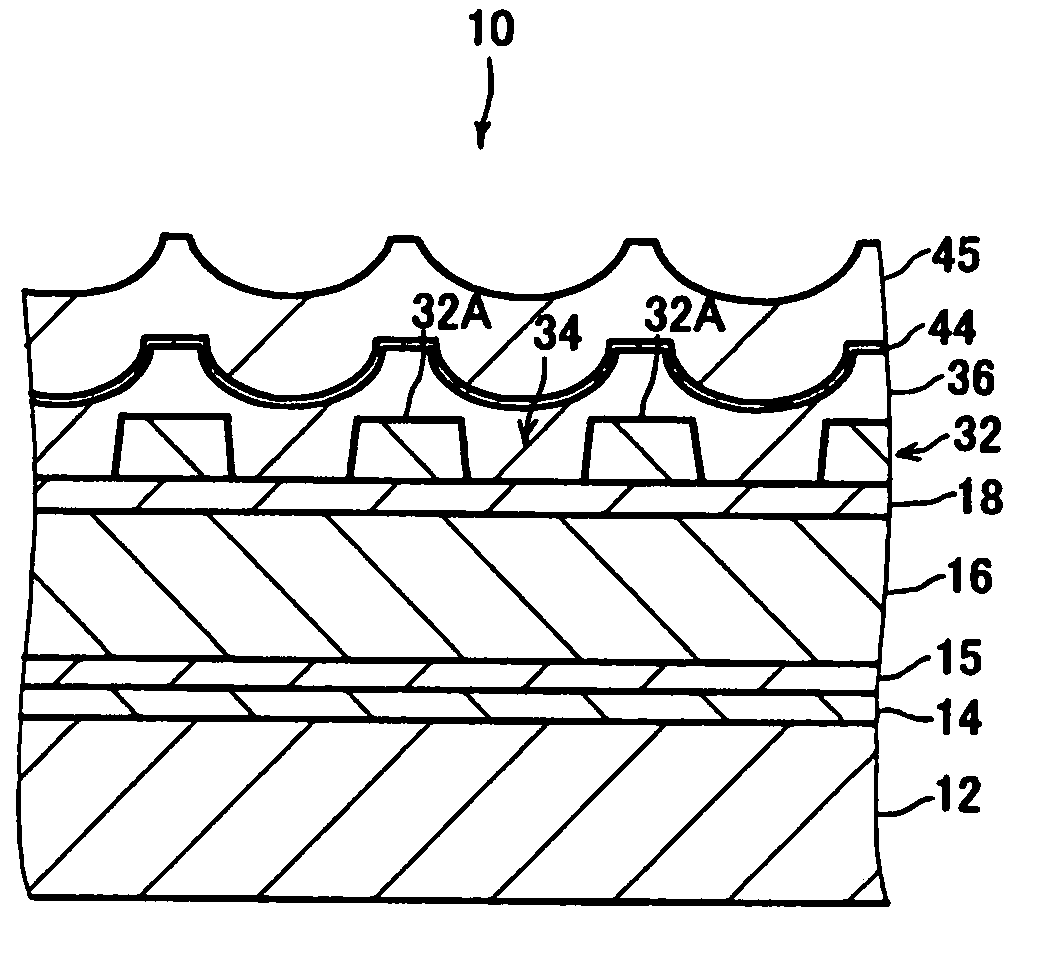
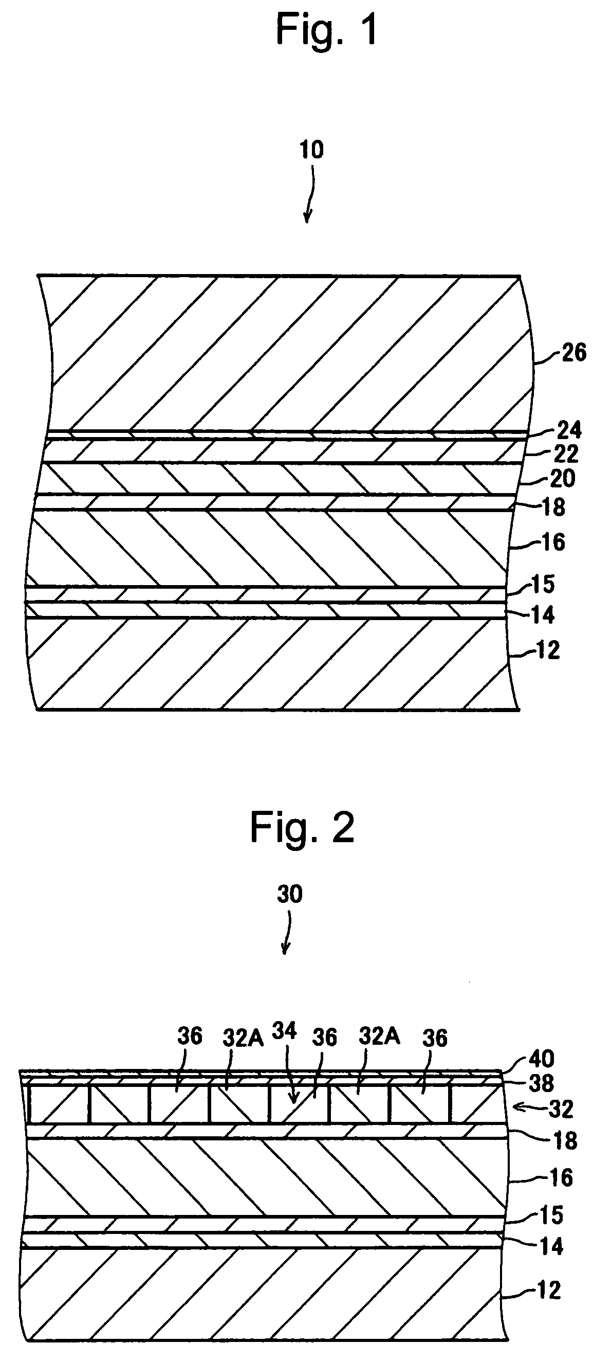
[0103]In accordance with the aforementioned first and second exemplary embodiments, nine types of samples A to J were prepared, ten pieces for each type. More specifically, ninety workpieces 10 were first prepared which had a substrate 12 of a diameter of 48 mm and a recording layer 32 with the following concavo-convex patterns.

[0104]Track pitch: 150 nm

[0105]Width of the convex portion: 90 nm

[0106]Width of the concave portion: 60 nm

[0107]Step height of concavo-convex pattern (the depth of the concave portion 34): 18 nm

[0108]Range of the concavo-convex pattern formed: within the radii of 16 to 18 mm from the center

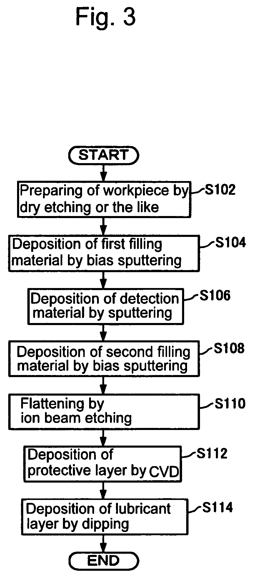
[0109]Then, by bias sputtering, the first filling material 36 was deposited on the recording layer 32 of the workpiece 10 in a thickness greater than the depth of the concave portion 34 to thereby fully fill the concave portion 34 with the first filling material 36. The bias sputtering was carried out under the following conditions. Note that the first filling material 36 w...

working example 2

[0134]In accordance with the third exemplary embodiment described above, ten samples of one type (K) were prepared. Note that the concavo-convex pattern of the recording layer 32 over the workpiece 10 was the same as that of A to J according to the aforementioned Working Example 1. Furthermore, there are many points in the manufacturing conditions that were common to those of A to J according to the aforementioned Working Example 1, and those common points will not be repeatedly explained.

[0135]Ten workpieces 10 having the concavo-convex patterned recording layer 32 were prepared, and the first filling material 36 was deposited on the recording layer 32 of these workpieces 10 in a thickness less than the depth of the concave portions 34. More specifically, the first filling material 36 was deposited in a thickness of 2 nm (the thickness of the first filling material 36 in the concave portion 34).

[0136]Then, by sputtering, the detection material 44 was deposited on the first filling ...

working example 3

[0141]In contrast to E of the aforementioned Working Example 1, ten samples of one type (L) were prepared which employed a different concavo-convex pattern for the recording layer 32. More specifically, the samples prepared were provided with a recording layer 32 which had the following concavo-convex pattern with the recording elements 32A wider than those of E according to Working Example 1.

[0142]Track pitch: 300 nm

[0143]Width of the convex portion: 180 nm

[0144]Width of the concave portion: 120 nm

[0145]Step height of concavo-convex pattern (the depth of the concave portion 34): 18 nm

[0146]Range of the concavo-convex pattern formed: within the radii of 16 to 18 mm from the center

[0147]Note that the other conditions were the same as those of E according to the aforementioned Working Example 1.

[0148]After the flattening process, by AFM, the step height between the top surface of the recording element 32A and the top surface of the first filling material 36 filling the concave portion...


PUM

PropertyMeasurementUnit
thicknessaaaaaaaaaa
thicknessaaaaaaaaaa
thicknessaaaaaaaaaa

Abstract

A method for manufacturing magnetic recording media is provided, by which a magnetic recording medium that has a recording layer formed in a concavo-convex pattern, a sufficiently flat surface, and good recording / reproducing properties can be manufactured. The method includes the steps of: depositing a first filling material over a workpiece to cover recording elements formed as convex portions of the concavo-convex pattern, and to fill at least part of a concave portion; depositing a detection material over the first filling material; depositing a second filling material over the detection material; and irradiating a surface of the workpiece with a process gas to flatten the surface. In the flattening step, a component of the detection material removed from and flying off the workpiece is detected to stop the irradiation with the process gas based on a result of detecting the component of the detection material.

Description

BACKGROUND OF THE INVENTION[0001]1. Field of the Invention[0002]The present invention relates to a method for manufacturing a magnetic recording medium having a recording layer formed in a concavo-convex pattern.[0003]2. Description of the Related Art[0004]Conventional magnetic recording media such as hard disks have been significantly improved in areal density, e.g., by employing finer magnetic grains or alternative materials for the recording layer(s) and by advanced microprocessing of magnetic heads. Although further improvements in areal density are still being sought, these conventional approaches to the improvement of areal density have already reached their limits due to several problems that have arisen. These problems include the limited accuracy of microprocessing of magnetic heads, erroneous recording of information on tracks adjacent to the target track due to spread of a recording magnetic field produced by the magnetic head, and crosstalk during reproducing operations....

Claims


Application Information

Patent Timeline
Patent Type & Authority Patents(United States)
IPC IPC(8): B05D5/12C23F1/00G11B7/24G11B5/33B44C1/22B05D3/00
CPCB82Y10/00G11B5/855G11B5/82G11B5/743
Inventor SUWA, TAKAHIROHATTORI, KAZUHIROOKAWA, SHUICHI
Owner TDK CORPARATION
Why Eureka
Try Eureka