Magnetoresistive effect thin-film magnetic head

Inactive Publication Date: 2005-03-22
TDK CORPARATION
View PDF14 Cites 5 Cited by
  • Summary
  • Abstract
  • Description
  • Claims
  • Application Information

AI Technical Summary

Benefits of technology

It is therefore an object of the present invention to provide an MR thin-film magnetic head having a TMR element or a CPP-GMR element for example, whereby the frequency characteristics of the MR thin-film magnetic head can be greatly improved.
Since at least a part of the insulation gap layer formed between the lower shield layer and the upper shield layer is made of an insulation material with a dielectric constant lower than that of Al2O3, the capacitance Cshield between the lower shield layer and the upper shield layer decreases. As a result, the frequency characteristics of the thin-film magnetic head is greatly improved.
Contrary to this, as shown in FIG. 6, when the capacitance Cshield between the shield layers is 1 pF, even if the resistance RTMR is higher than 300 Ω, the cut-off frequency fc can be fc>500 MHz. For the resistance RTMR higher than 300 Ω that is a sufficiently realizable value, the frequency characteristic of the thin-film magnetic head can be greatly improved by making the capacitance Cshield between the shield layers smaller. The capacitance CTMR of the TMR element or CPP-GMR element itself is much smaller than the capacitance Cshield between the shield layers (less than one tenth), and therefore can be of little or no problem.

Problems solved by technology

However, such an insulating material is difficult to make and has been the bottleneck for providing a CIP-GMR element used in a high density HDD apparatus.
These resistance RTMR and capacitances CTMR and Cshield form a low-pass filter causing serious deterioration of the frequency characteristics.

Method used


Image

  • Magnetoresistive effect thin-film magnetic head
  • Magnetoresistive effect thin-film magnetic head
  • Magnetoresistive effect thin-film magnetic head

Examples


Embodiment Construction

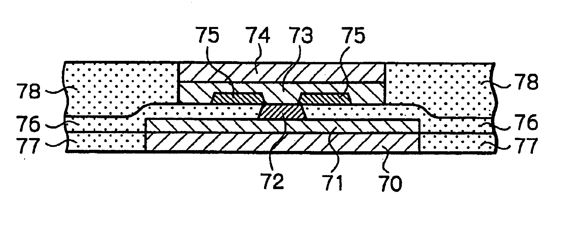
FIG. 7 schematically illustrates an outline of the configuration of a lower shield layer, an upper shield layer, and lead conductors of a TMR thin-film magnetic head before MR height or throat height polishing as a preferred embodiment according to the present invention, FIG. 8 illustrates an A—A line section of FIG. 7, and FIG. 9 illustrates a B—B line section of FIG. 7.

In FIG. 7, only the lower shield layer, the upper shield layer, the lead conductors connected to the lower shield layer and upper shield layer, and terminal electrodes are shown, but the rest of the structure are omitted. In FIGS. 8 and 9, layers laminated on the upper surface of the upper shield layer are omitted.

Referring to these figures, reference numeral 70 denotes a lower shield layer also serving as an electrode, laminated on a substrate, not shown, 71 denotes a lower gap layer serving also as an electrode, made of a nonmagnetic electrically conductive material, that is laminated on the lower shield layer 70 ...


PUM


Abstract

An MR thin-film magnetic head includes a lower shield layer, an upper shield layer, a MR multilayer sandwiched between the lower shield layer and the upper shield layer, the MR multilayer being electrically connected with the lower shield layer and the upper shield layer, a current flowing through the MR multilayer in a direction perpendicular to surfaces of layers, and an insulation gap layer formed between the lower shield layer and the upper shield layer. At least a part of the insulation gap layer is made of an insulation material with a dielectric constant lower than that of Al2O3.

Description

FIELD OF THE INVENTIONThe present invention relates to a magnetoresistive effect (MR) thin-film magnetic head that is applicable to a hard disk drive (HDD) apparatus and provided with a tunnel magnetoresistive effect (TMR) element or a current perpendicular to the plane giant magnetoresistive effect (CPP-GMR) element, in which a current flows in a direction perpendicular to surfaces of layers.DESCRIPTION OF THE RELATED ARTRecently, in order to satisfy the demand for higher recording density in an HDD apparatus, higher sensitivity and larger output of a thin-film magnetic head are required. A TMR element and a CPP-GMR element meet these requirements and are beginning to receive attention. The TMR element, disclosed in Japanese patent publication No. 04103014A for example, utilizes a ferromagnetic tunnel effect and has a multi-layered structure including a lower ferromagnetic thin-film layer, a tunnel barrier layer and an upper ferromagnetic thin-film layer. The CPP-GMR element is one...

Claims


Application Information

Patent Timeline
IPC IPC(8): G11B5/39G11B5/31H01L43/08
CPCB82Y10/00B82Y25/00G11B5/3909G11B5/3903G11B5/3133
Inventor SHIMAZAWA, KOJI
Owner TDK CORPARATION
Why Eureka
Try Eureka