

Receiving device
- Summary
- Abstract
- Description
- Claims
- Application Information
AI Technical Summary
Benefits of technology
Problems solved by technology
Method used
Image

Examples
first embodiment
[0047]Hereinafter, embodiments of the disclosure are described in detail with reference to the figures.
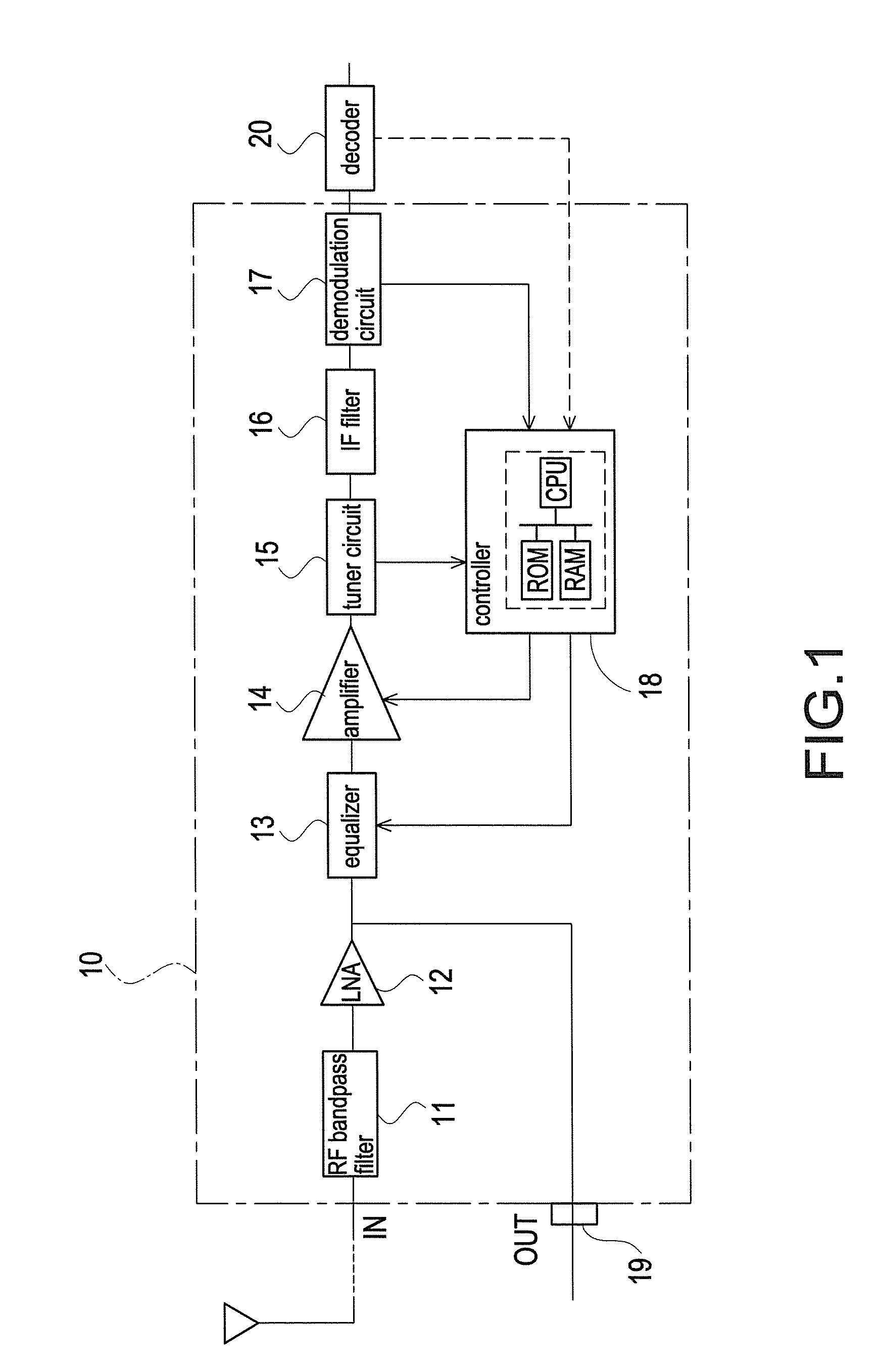
[0048]FIG. 1 illustrates a receiving device according to an embodiment of the invention by a block diagram. The receiving device is capable of receiving broadcasting signals of a BS broadcasting band and a CS broadcasting band.
[0049]Referring to the figure, a tuner 10 includes a RF bandpass filter (BPF) 11 that is connected with an antenna terminal and is set with a pass frequency band in a receiving frequency band, a low noise amplifier (LNA: high frequency amplifier) 12 that amplifies an output of the RF bandpass filter 11, an equalizer 13 used primarily for tilt correction, an amplifier 14 that amplifies an output of the equalizer 13 as required, a tuner circuit 15 that receives a broadcasting signal of a desired channel, an IF filter (LPF: low-pass filter) 16 that inputs an intermediate frequency signal outputted by the tuner circuit 15 to reduce an undesired signal component, ...
second embodiment
[0077]In the aforementioned embodiment, the controller 18 obtains the C / N value from the demodulation circuit 17 for determining the quality of the reception condition. However, an index for determining the quality of the reception condition is not limited to the C / N value.
[0078]In another embodiment, the controller 18 may obtain the bit error rate (BER) from the decoder 20. An error is less likely to occur during decoding if the reception condition is good. Thus, the decoder 20 is able to determine the reception condition by referring to the BER.
[0079]In this way, the reception condition detector detects the BER value of each channel to determine the reception condition.
third embodiment
[0080]FIG. 6 is a diagram showing a screen for selecting a broadcasting wave to be viewed.
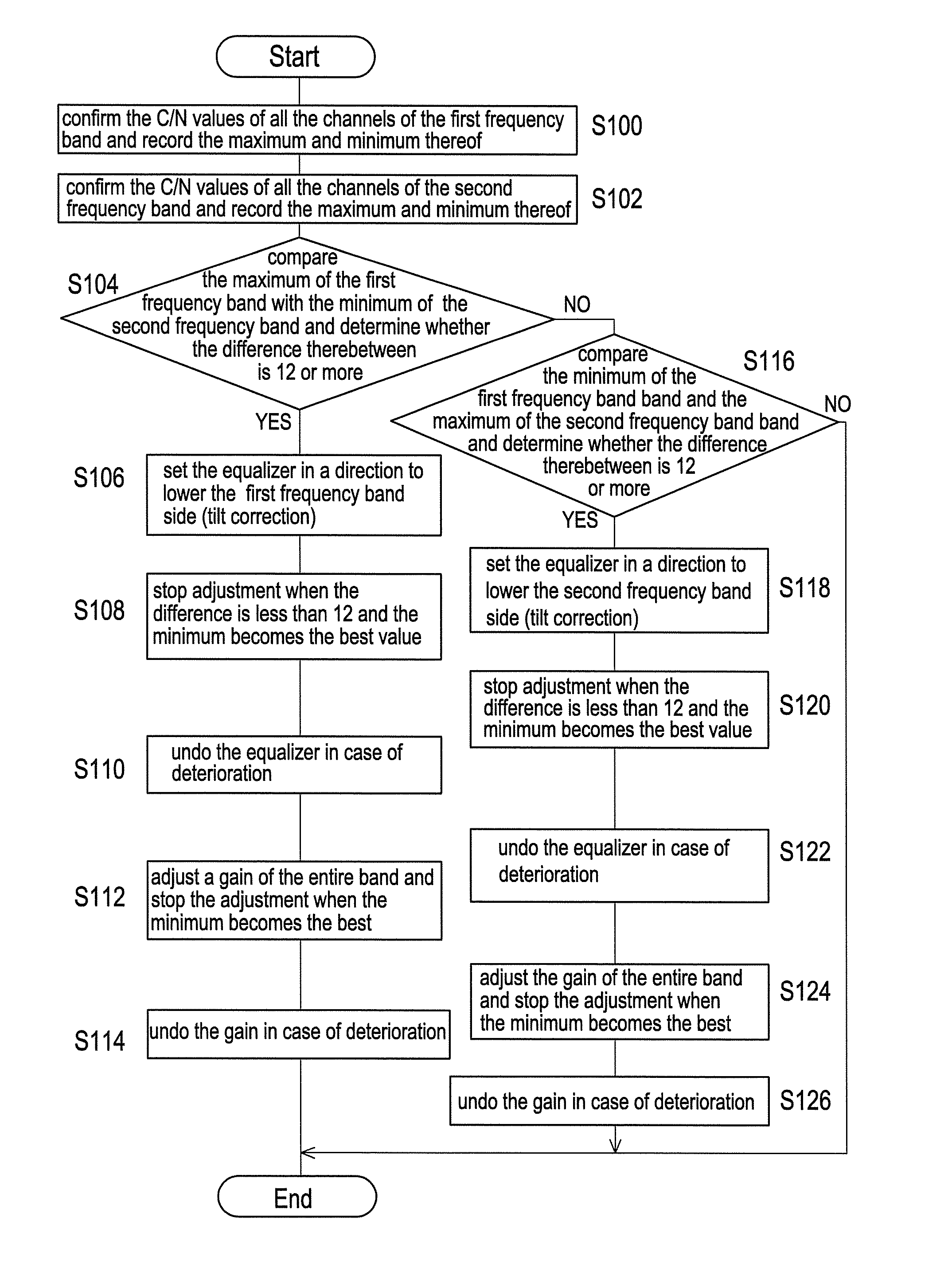
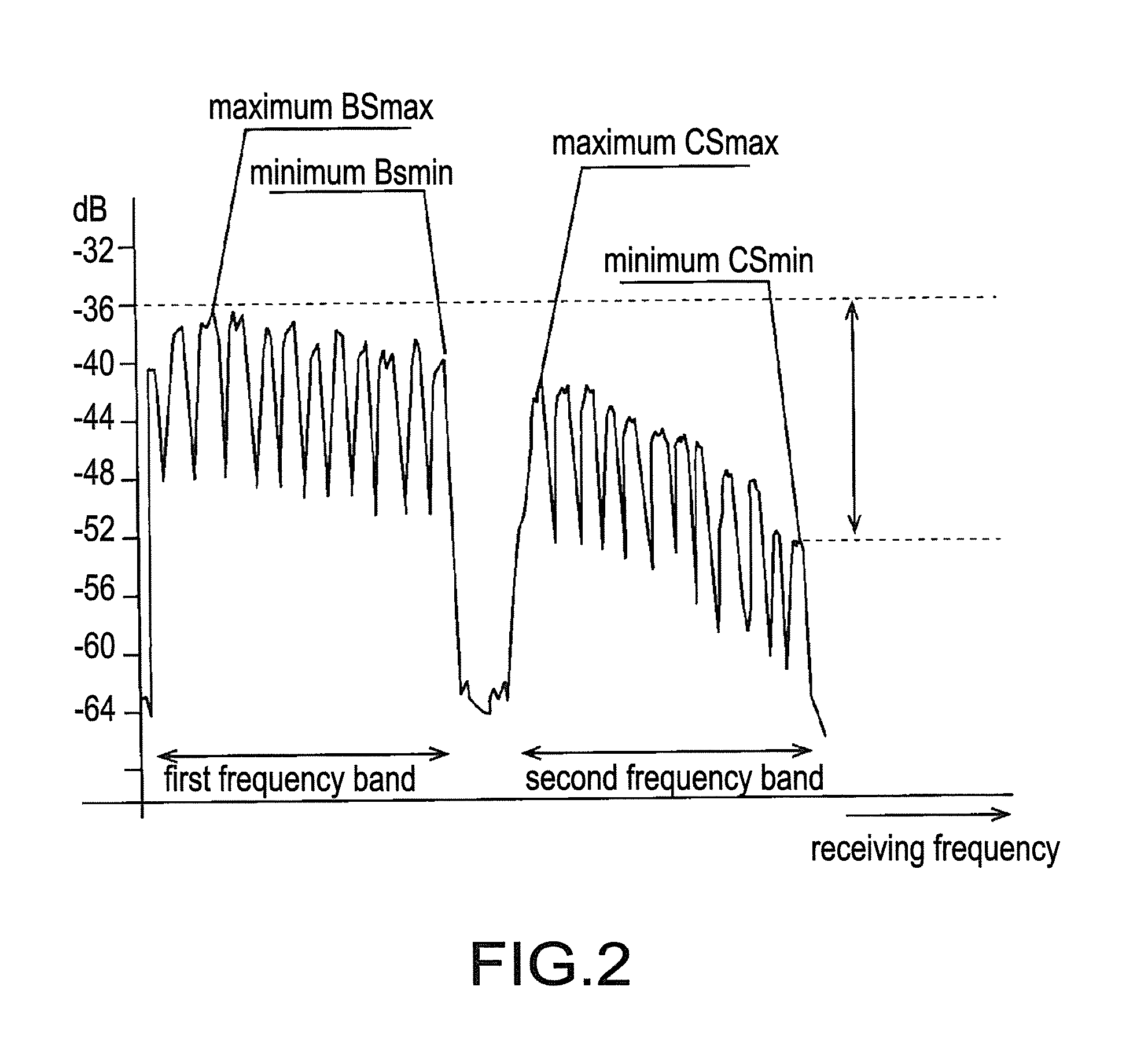
[0081]As shown in FIG. 2, even though the reception condition of the second band (the CS band) may be bad, it will not cause any problem if the user does not view the second band (the CS band) anyway. However, if the equalizer 13 carries out the tilt correction to lower the signal intensity of the first band (the BS band), the C / N value deteriorates.
[0082]Therefore, in a machine, e.g., a hard disk recording and reproducing apparatus, that incorporates the tuner 10, a screen is displayed for selecting the broadcasting wave to be viewed during channel setup, as shown in FIG. 6. If the user sees the screen during channel setup and has no interest in the CS broadcasting wave, the user may uncheck a check mark. In the screen, it is also possible to uncheck the check mark for the BS broadcasting.
[0083]The tilt correction is not performed at least when the check mark for the CS broadcasting is uncheck...
PUM
 Abstract
Description
Claims
Application Information