Failure diagnosing apparatus for an engine cooling water temperature sensor

a technology for failure diagnosis and engine cooling water temperature sensor, which is applied in the direction of instruments, electrical control, heat measurement, etc., can solve the problem of relaxed frequency limitation of failure diagnosis process, and achieve the effect of accurate determination and cost saving

Inactive Publication Date: 2005-06-21
HONDA MOTOR CO LTD
View PDF16 Cites 10 Cited by
  • Summary
  • Abstract
  • Description
  • Claims
  • Application Information

AI Technical Summary

Benefits of technology

[0008]According to the invention, since it can be determined whether behavior of the first sensor is normal based on the comparison with behavior of the second sensor, it can be prevented that a normal first sensor is incorrectly determined as being faulty. Since both of the first and second sensors are placed under the same external environment, the first sensor exhibits a similar behavior to the second sensor if the first sensor is normal. By taking into account a behavior of the second sensor, it is more accurately determined whether the behavior of the first sensor is normal. There is no need to consider the influence of the external environment so as to determine whether the behavior of the first sensor is normal.
[0009]A timer that measures an elapsed time after the engine stops is not required, which leads to cost savings. Since the failure diagnosing process can be performed before a predetermined time elapses from the time when the engine stops, a limitation for the frequency of performing the failure diagnosing process is relaxed.

Problems solved by technology

Since the failure diagnosing process can be performed before a predetermined time elapses from the time when the engine stops, a limitation for the frequency of performing the failure diagnosing process is relaxed.

Method used


Image

  • Failure diagnosing apparatus for an engine cooling water temperature sensor
  • Failure diagnosing apparatus for an engine cooling water temperature sensor
  • Failure diagnosing apparatus for an engine cooling water temperature sensor

Examples


Embodiment Construction

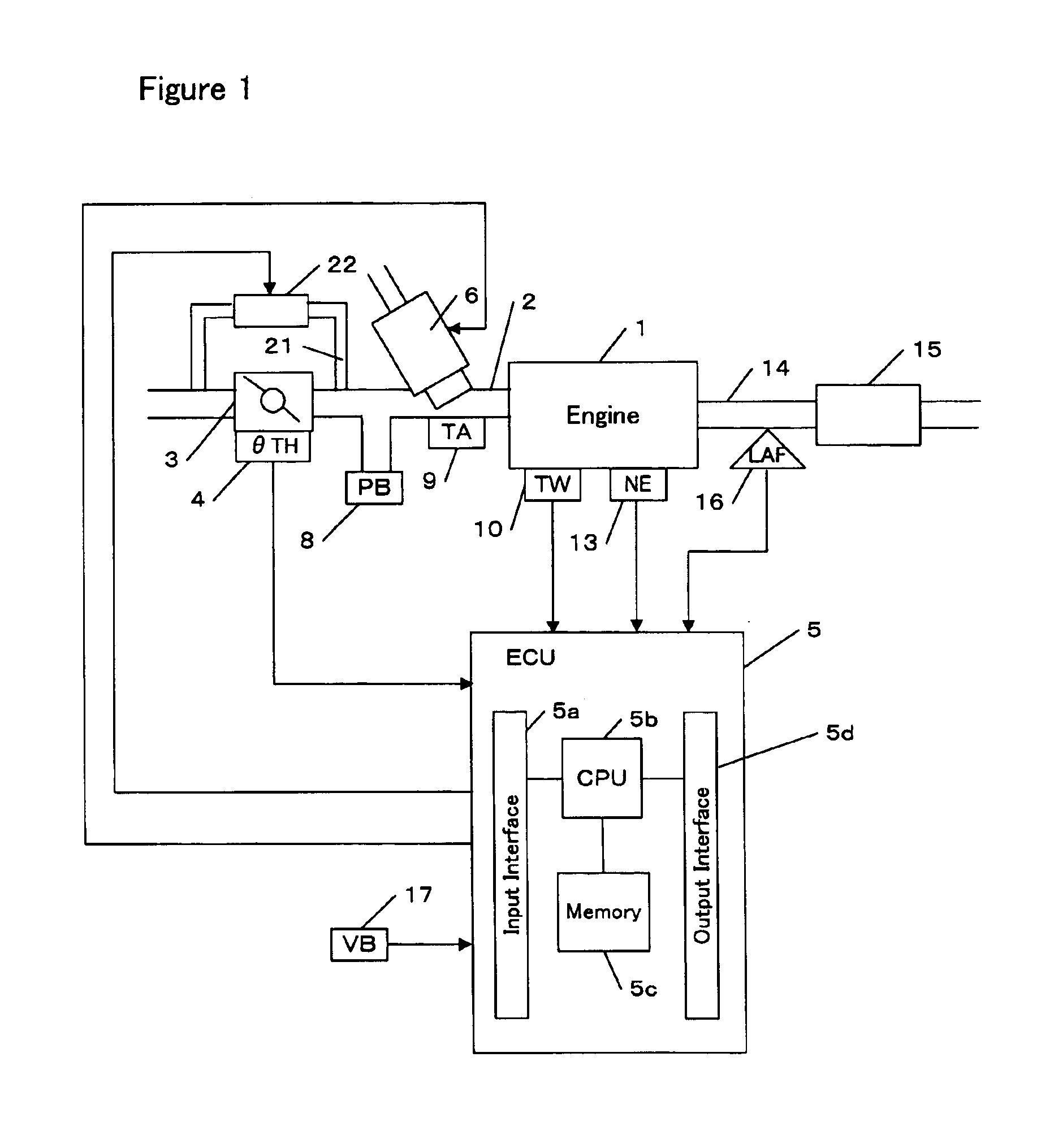
[0026]Referring to the drawings, specific embodiments of the invention will be described. FIG. 1 is a block diagram showing an engine and its control unit in accordance with one embodiment of the invention.

[0027]An electronic control unit (hereinafter referred to as an ECU) 5 comprises an input interface 5a for receiving data sent from each part of the engine 1, a CPU 5b for carrying out operations for controlling each part of the engine 1, a memory 5c including a read only memory (ROM) and a random access memory (RAM), and an output interface 5d for sending control signals to each part of the engine 1. Programs and various data for controlling each part of the vehicle are stored in the ROM. A program for performing a failure diagnosing process according to the invention, data and tables used for operations of the program are stored in the ROM. The ROM may be a rewritable ROM such as an EEPROM. The RAM provides work areas for operations by the CPU 5a, in which data sent from each pa...


PUM

PropertyMeasurementUnit
temperatureaaaaaaaaaa

Abstract

The invention provides a failure diagnosing apparatus having a first sensor for detecting a temperature of cooling water of an engine mounted on a vehicle and a second sensor for detecting a temperature associated with the engine. The apparatus calculates a first difference between a temperature detected by the first sensor at the time when the engine stops in a previous operating cycle and a temperature detected by the first sensor at the time when the engine starts in a current operating cycle is calculated. The apparatus also calculates a second difference between a temperature detected by the second sensor at the time when the engine stops in the previous operating cycle and a temperature detected by the second sensor at the time when the engine starts in the current operating cycle. It is determined whether the first sensor is faulty based on the first difference and the second difference.

Description

BACKGROUND OF THE INVENTION[0001]The present invention relates to an apparatus for diagnosing failure of a sensor that detects the temperature of cooling water of an internal combustion engine.[0002]A radiator mounted on a vehicle supplies cooling water to an internal combustion engine (hereinafter referred to as “engine”) to cool the engine. A sensor for detecting temperature of the cooling water is provided on the engine. This sensor will be hereinafter referred to as an “engine water temperature sensor.” The temperature detected by the engine water temperature sensor is used for various controls of the engine. Appropriate controls of the engine require accurate detection of the engine water temperature.[0003]Japanese Patent Application Unexamined Publication (Kokai) No. 2000-45851 shows a method for detecting a failure of the engine water temperature sensor. According to the method, an output of the engine water temperature sensor is monitored over a predetermined time period. If...

Claims


Application Information

Patent Timeline
Patent Type & Authority Patents(United States)
IPC IPC(8): F01P11/14F01P11/16F02D41/22F02D45/00F02D41/06
CPCF01P11/16F02D41/222F01P2025/08F01P2025/13Y02T10/40F02D41/062F02D2200/0414F01P2031/00G01K15/007
Inventor TSUKAMOTO, TOSHINORITAKASUKA, YOSHITAKAGOSYO, EISAKU
Owner HONDA MOTOR CO LTD
Why Eureka
Try Eureka