
Process and apparatus for embossing precise microstructures and embossing tool for making same

a microstructure and precise technology, applied in dough embossing machines, solid-state devices, butter manufacturing, etc., can solve the problems of limited processing speed (and thus material volume), formation of some embossed surfaces, and complex modification of the geometry of the tool surfa

Inactive Publication Date: 2005-06-21
AVERY DENNISON CORP
View PDF69 Cites 114 Cited by
  • Summary
  • Abstract
  • Description
  • Claims
  • Application Information

AI Technical Summary

Benefits of technology

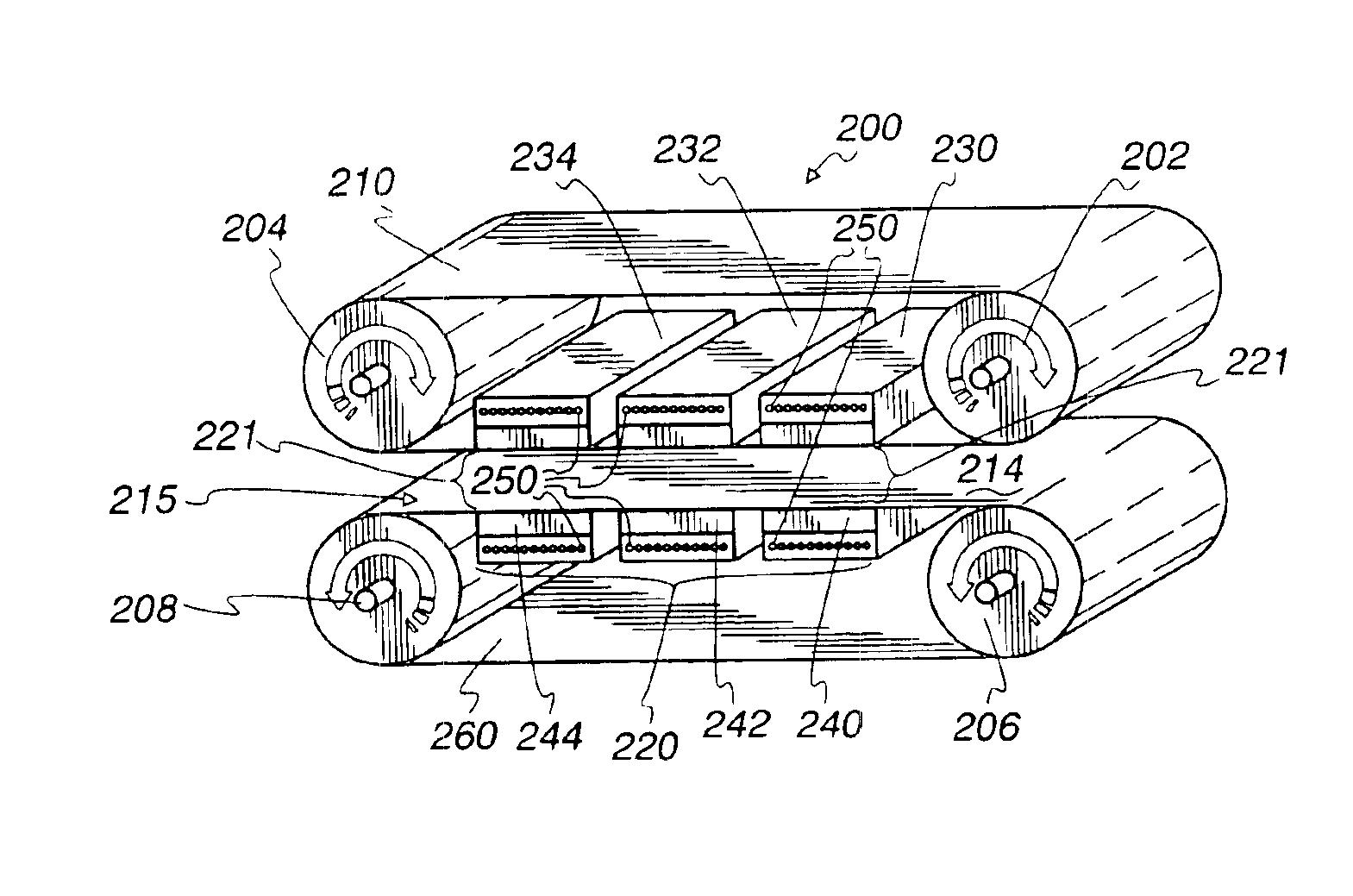
[0028]As noted, the present invention offers numerous advantages and relates to a process and apparatus for making thermoplastic products having precision microstructured patterns comprising the steps of providing a continuous press with an upper set of rollers, a lower set of rollers, an upper belt disposed about the upper set of rollers, a lower belt disposed about the lower set of rollers, the upper and lower belts defining a relatively flat reaction zone therebetween, the reaction zone including a heating station, a cooling station and pressure producing means; feeding a thermoplastic film between the bands and through the reaction zone; heating the material to an embossing temperature Te above the glass transition temperature Tg of the thermoplastic material, (e.g. around 100° to 150° F. / 38° C. to 66° C. above Tg); applying on elevated embossing pressure to the material, (e.g. about 250 psi / 1.7 MPa); cooling the material (e.g. well below Tg); while maintaining the elevated pressure on the material.
[0045]Surface roughness for microfluidic applications that allow for low friction and minimal surface drag, all resulting in smooth continuous non-diffusive flow, allowing the fluid flowing laminar.
[0046]The avoidance of residual stresses by providing essentially stress free microstructures. This is critical for some optical, FSA, and for microfluidic applications were the detection mechanisms uses fluorescent polarization technology. Materials with stress generally have strand orientation, which acts like a polarizing lens. Materials that contain residual stresses may relax that stress during subsequent processing or during the life cycle of the product, resulting in dimensional instability.

Problems solved by technology

The prior apparatus and process work well to produce rolls of film that are effectively 48″ (122 cm) wide (52″ / 132 cm at salvage), but such equipment and processes have several inherent disadvantages.
First, the process speed (and thus the volume of material) is limited by the time needed to heat, mold and freeze the film.
Also, the pressure surface area and thus the time available to provide adequate pressure by the pressure rollers, impose certain special constraints; and then cooling the material.
Finally the formation of some embossed surfaces while the tool is in a curved condition requires complex modification of the geometry of the tool surface, because the thermoplastic elements are formed while on a curved surface but generally used later while on a flat surface.
That process is not commercially practical because of its perceived inability to accurately reproduce microstructures because of indexing mold movement and the relatively small volume (caused by mold size) and speed.
Also, the equipment and process is non-continuous.
However, such presses, without modifications, are neither designed for nor capable of embossing precise microstructures on the material passing through the press.
Of course, friction is substantial on the product, and double band presses overcome this by several systems.

Method used


Image

  • Process and apparatus for embossing precise microstructures and embossing tool for making same
  • Process and apparatus for embossing precise microstructures and embossing tool for making same
  • Process and apparatus for embossing precise microstructures and embossing tool for making same

Examples


Embodiment Construction

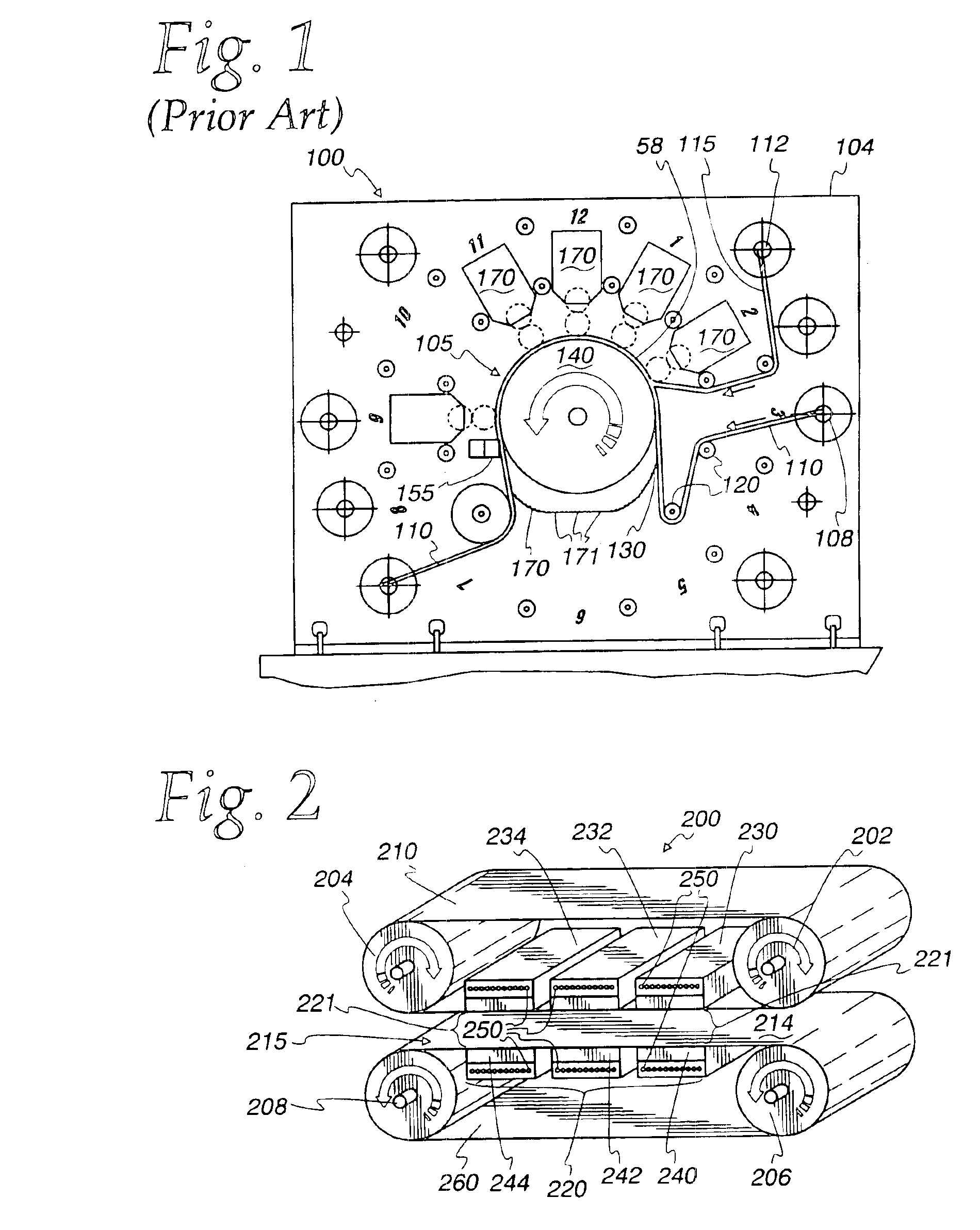
[0063]Referring now to FIG. 1, a modified form of an existing embossing machine 100 for producing an embossed substrate or film 110 is shown in elevation, suitably mounted on a floor 102. This machine is similar in operation to those disclosed in aforementioned U.S. Pat. No. 4,486,363, but instead uses a single large roller and different pressure rollers. It is disclosed in greater detail in commonly assigned U.S. application Ser. No. 09 / 776,281, filed Feb. 2, 2001, entitled “Method of Making a Flexible Substrate Containing Self-Assembling Microstructures,” incorporated herein in full by reference. The machine 100 includes a frame 104, centrally mounted on which is an embossing means 105. A supply reel 108 of unembossed thermoplastic film 110 and a supply reel 112 of flexible plastic carrier film 115 are mounted on the frame 104. The film 110 may be 0.005 inches (125 μm) thick and the carrier film 115 may be about 0.002 inches (50 μm) thick. The film 110 and the carrier film 115 are...


PUM

PropertyMeasurementUnit
depthaaaaaaaaaa
pressureaaaaaaaaaa
pressureaaaaaaaaaa

Abstract

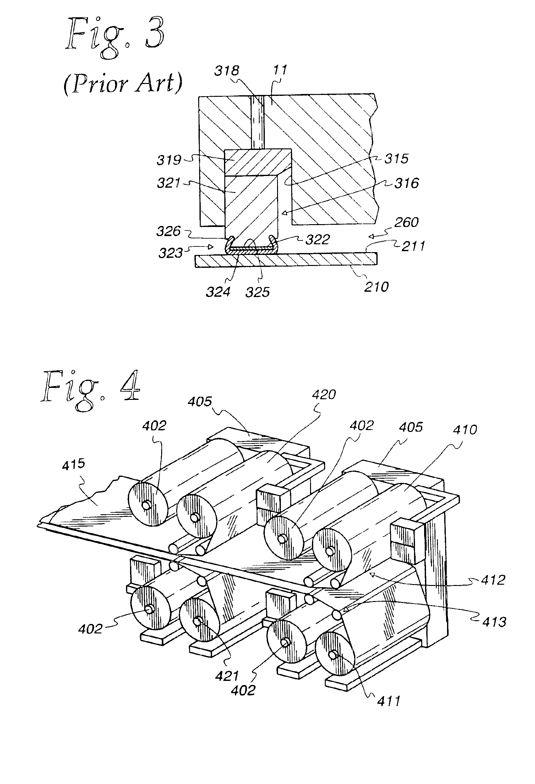
A process and apparatus for embossing thermoplastic products having precise microstructured surfaces including using a continuous press having upper and lower belts with the embossing pattern(s); feeding thermoplastic material through the press where heat and pressure are applied to form the embossed pressure microstructure, and cooling the embossed material, all while maintaining pressure. A continuous embossing tool is provided by welding segments together, the welds including interface material at the weld joint which is of a different material than the segment material to increase the tensile strength.

Description

RELATED APPLICATIONS[0001]This application is a continuation-in-part of U.S. application Ser. No. 09 / 596,240 filed Jun. 16, 2000, now abandoned, and Ser. No. 09 / 781,756, filed Feb. 12, 2001, now abandoned, commonly assigned to applicant's assignee, the disclosure and subject matter of each of which is incorporated in full herein by reference.BACKGROUND OF THE INVENTION[0002]1. Technical Field[0003]The present invention relates to a process and apparatus for embossing material with precise detail, and more particularly, to a process and apparatus for making products of thermoplastic material having surfaces with precision microstructures, as defined below. It also pertains to a tool and method of making a tool for such embossing.[0004]2. Background Art[0005]Processes and apparatus for embossing precision optical patterns such as microcubes, in a resinous sheet or laminate, is well known as referenced in U.S. Pat. Nos. 4,486,363; 4,478,769; 4,601,861; 5,213,872; and 6,015,214, which p...

Claims


Application Information

Patent Timeline
Patent Type & Authority Patents(United States)
IPC IPC(8): B29C43/48B29C43/22B29C43/44B29C59/04B29C33/42B23K26/20B23K26/26B23K26/32B29C43/26B29L7/00
CPCB23K26/203B23K26/26B23K26/3206B23K26/3213B23K26/3233B29C43/222B29C43/26B29C43/48B29C59/04B23K2203/04B29C2059/023B29C2043/483B29C33/424B23K26/32B23K26/211B23K26/323B23K2103/05B23K2103/08B23K2103/42B23K2103/50H01L2924/15153
Inventor THIELMAN, W. SCOTTPRICONE, ROBERT M.
Owner AVERY DENNISON CORP
Learn More