Connector having a simple structure assuring a stable mounting operation

a simple structure and connector technology, applied in the direction of coupling device connection, substation/switching arrangement details, coupling protective earth/shielding arrangement, etc., can solve the problems of difficult to obtain electrically stable loop, difficult to flow grounding signal towards the back shell, etc., to achieve stable operation of mounting the connector, stable operation of attaching the connector, and simple structure

Inactive Publication Date: 2005-06-21
JAPAN AVIATION ELECTRONICS IND LTD
View PDF7 Cites 22 Cited by
  • Summary
  • Abstract
  • Description
  • Claims
  • Application Information

AI Technical Summary

Benefits of technology

[0007]It is therefore an object of the present invention to provide a connector having a simple structure assuring a stable operation of mounting the connector to a circuit board and a stable operation of attaching the connector to a chassis panel.
[0008]It is another object of the present invention to provide a connector which is enhanced in connecting strength between a front shall and a back shell.
[0009]It is still another object of this invention to provide a connector sufficiently enhanced in shielding function.

Problems solved by technology

However, since the grounding member is required, the number of components is increased and assembling requires a lot of time and labor (a number of steps), resulting in an increase in cost.
Therefore, a grounding signal is difficult to flow towards the back shell.
In addition, if the contact between the front shell and the separate component is insufficient, an electrically stable loop can not be obtained.
Such reflection causes electromagnetic interference to induce a noise.

Method used


Image

  • Connector having a simple structure assuring a stable mounting operation
  • Connector having a simple structure assuring a stable mounting operation
  • Connector having a simple structure assuring a stable mounting operation

Examples


Embodiment Construction

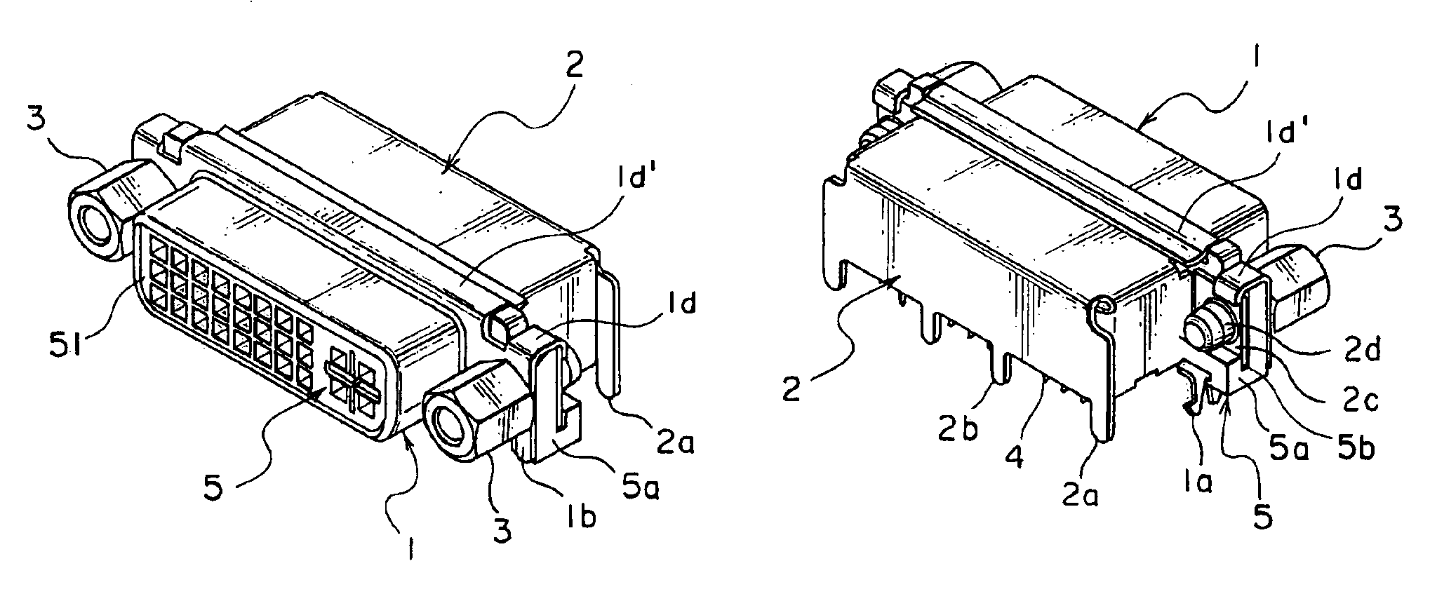
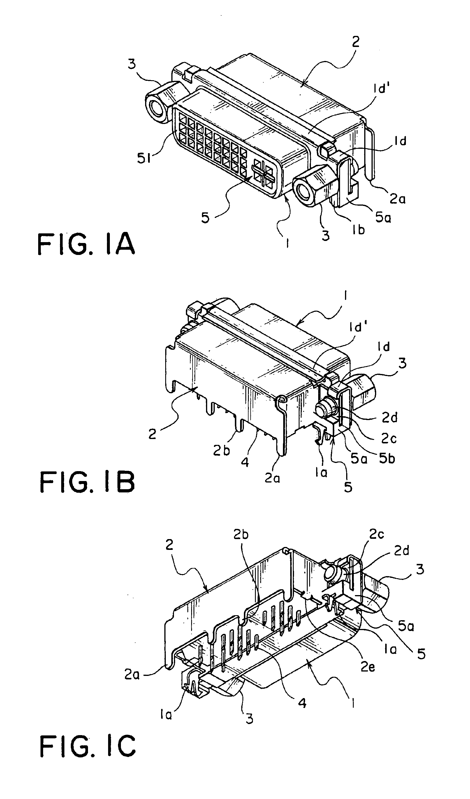
[0034]Referring to FIGS. 1A to 1C, description will be made of a whole of a connector according to an embodiment of this invention.

[0035]The connector illustrated in the figures comprises a plurality of conductive contacts 4 and an insulating housing 5 fixedly holding the contacts 4. The housing 5 has a fitting portion 51 covered by a conductive front shell 1. Each of the contacts 4 has an angled portion 4a covered with a conductive back shell 2, as also illustrated in FIG. 5B. The connector is mounted to a board such as a printed circuit board 7 as shown in FIG. 5B.

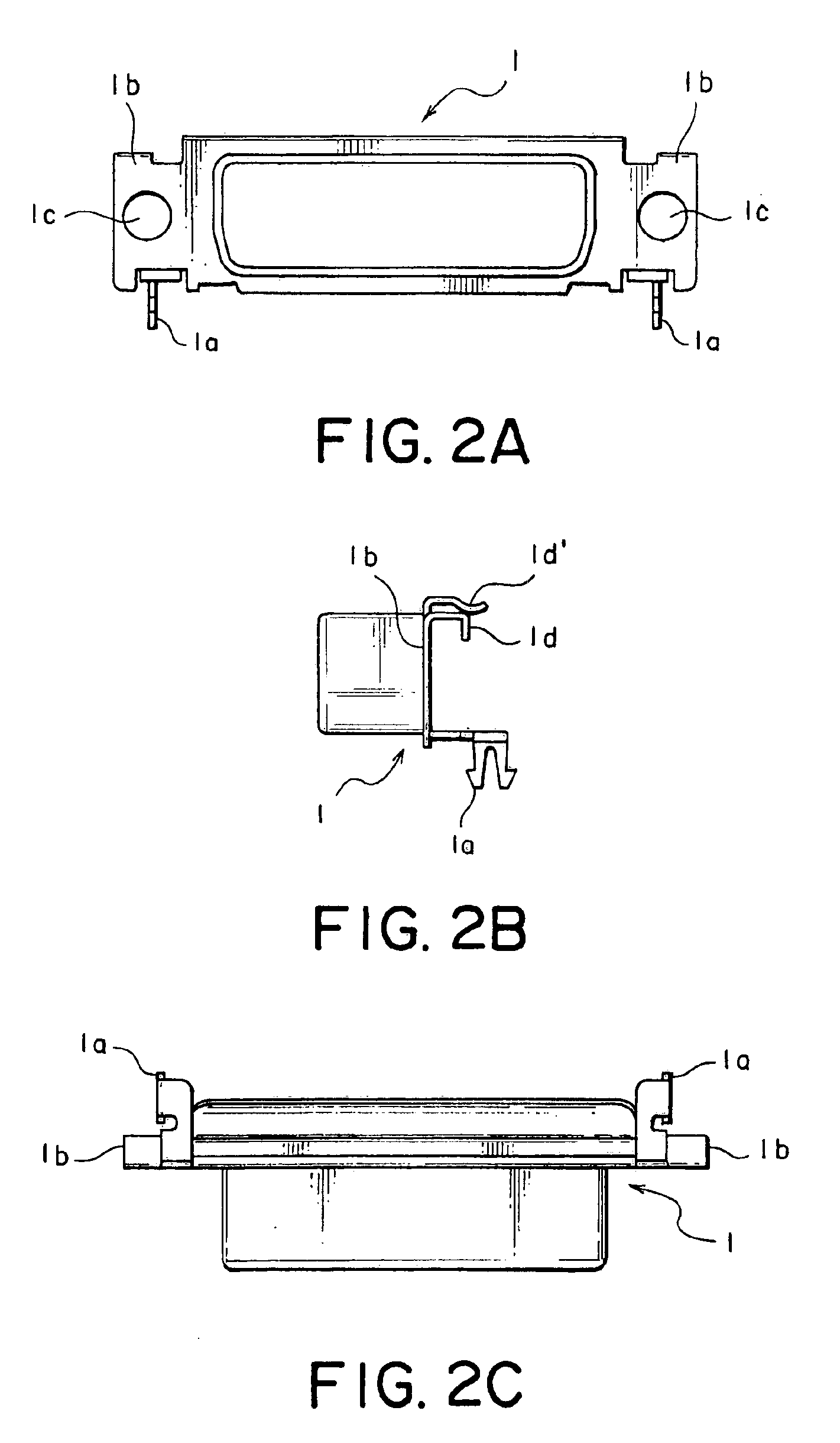
[0036]Referring to FIGS. 2A to 2C in addition, the front shell 1 has a pair of hooked terminals 1a and a pair of fixing portions 1b integrally formed on opposite sides thereof. The hooked terminals 1a are adapted to be connected to the circuit board 7. Each of the fixing portions 1b has an insertion hole 1c for inserting a screw 3. The front shell 1 is provided with a pair of lower contacting pieces 1d at the opposite si...


PUM


Abstract

A connector to be mounted to a board includes a contact having an angled portion, a housing having a fitting portion and fixedly holding the contact, and a conductive shell. The shell includes a front shell covering the fitting portion and a back shell covering the angled portion. The front shell has a terminal to be connected to the board and a fixing portion provided with an insertion hole allowing a screw to be inserted therethrough. The back shell has a terminal to be connected to the board and a fixed portion faced to the fixing portion. The fixed portion has a tap portion. The front and the back shells are fixed to the housing by screwing the screw through the insertion hole into the tap portion.

Description

[0001]This application claims priority to prior Japanese patent application JP 2003-288682, the disclosure of which is incorporated herein by reference.BACKGROUND OF THE INVENTION[0002]This invention relates to a connector having an electromagnetic shielding function and adapted to be mounted on a board such as a printed circuit board known in the art.[0003]A connector of the type is disclosed, for example, in U.S. Pat. No. 6,554,642 as an electrical connector. The electrical connector comprises an insulator housing surrounded by a back shell and a front shell which are made of conductive members, respectively. The back shell and the front shell are electrically connected to each other through mechanical contact at their portions. The front shell has a tap portion fixed via a screw to a casing panel or a chassis panel of an electric or electronic apparatus.[0004]When the electrical connector is mounted to a circuit board, the electrical connector is electrically connected to the cir...

Claims


Application Information

Patent Timeline
Patent Type & Authority Patents(United States)
IPC IPC(8): H01R13/74H01R13/648H01R12/70H01R13/60H01R13/658H01R13/73
CPCH01R12/707H01R12/7047H01R13/748H01R13/60H01R13/648
Inventor TANAKA, YUKITAKA
Owner JAPAN AVIATION ELECTRONICS IND LTD
Why Eureka
Try Eureka