Surgical devices having a biodegradable material with a therapeutic agent

a biodegradable material and surgical technology, applied in the field of surgical devices, can solve problems such as inability to biodegrad

Inactive Publication Date: 2005-06-21
P TECH +1
View PDF48 Cites 307 Cited by
  • Summary
  • Abstract
  • Description
  • Claims
  • Application Information

AI Technical Summary

Benefits of technology

[0013]The present invention may also provide a method of suturing body tissue. A portion of a suture is inserted into an opening in a retainer formed of a plastic material. At least a portion of the retainer is heated to a temperature in a transition temperature range of the plastic material forming the retainer. The suture is maintained at a temperature below the transition temperature range of a plastic material forming the suture while the retainer is heated. The plastic material of the retainer flows around the plastic material of the suture. A bonding of the plastic material of the retainer to the plastic material of the suture is effected by cooling the plastic material of the retainer to a temperature below its transition temperature range. The foregoing steps are performed without significant deformation of the plastic material of the suture.

Problems solved by technology

Further, it is not biodegradable.

Method used


Image

  • Surgical devices having a biodegradable material with a therapeutic agent
  • Surgical devices having a biodegradable material with a therapeutic agent
  • Surgical devices having a biodegradable material with a therapeutic agent

Examples


first embodiment

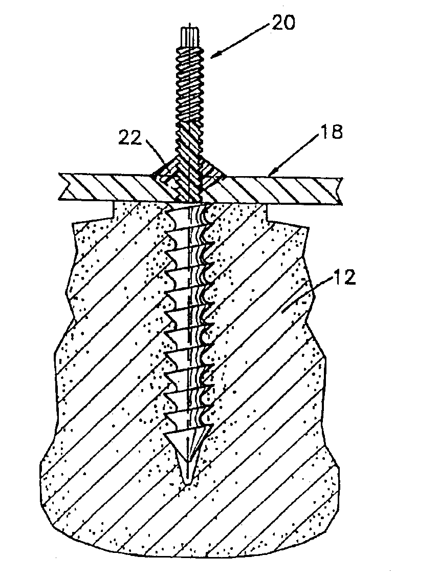
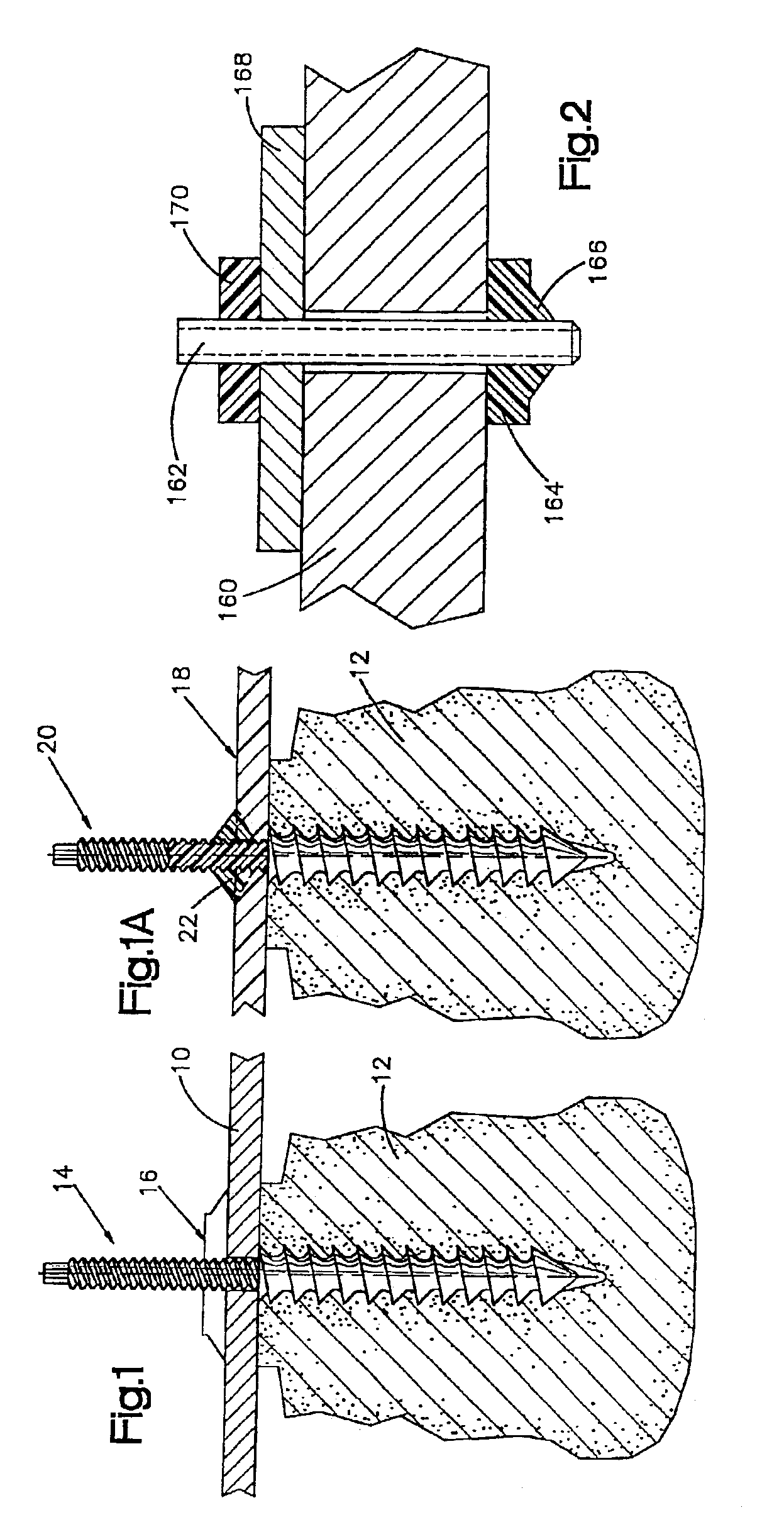
[0037]FIGS. 1 and 2 illustrate heat bonded assemblies including existing surgical objects such as plates, screws, etc. In FIG. 1, a bone plate 10 is secured to bone material 12 by a bone screw 14. The bone plate 10 and the bone screw 14 are both made of metal. Ordinarily, the bone screw 14 would be secured to the bone plate 10 by a metal nut threaded onto the bone screw 14 and run up adjacent the bone plate 10. However, such a connection can loosen and thus destroy the integrity of the assembly. Accordingly, in accordance with the present invention, a nut 16 is provided which is made of or includes a bondable material. The nut 16 is threaded on the bone screw 14 into abutting engagement with the bone plate 10. Then, the bondable material of the nut 16 is heated and softened to flow about the joint between the nut 16 and the bone plate 10, to bond the nut 16 to the bone plate 10. The nut 16 can also be bond to the bone screw 14 if desired for a stronger connection.

[0038]FIG. 1A illus...

second embodiment

[0051]It is difficult to tie a suture knot to itself or to slide it down through deep tissue in a limited working area (as in fiber optic surgery). Typically, the surgeon can often not work in a straight line but needs to use a suture loop (going through the tissue twice) to bring tissue together. Any such increase in the amount of tissue through which the suture must pass increases damage to tissue. Furthermore, mechanical tying or crimping of sutures or K-wires, especially of polymers or biodegradables which are generally smooth, does not produce connections which are as strong as desirable, and suture connections sometimes may come untied as a result.

[0052]In accordance with one of the features of the present invention, surgical connections for holding adjoining tissues together are secured by melting a fastener or anchor on the end of a suture, rather than by tying or by clipping the anchor on the end of the suture. (The term “suture” is used herein to refer to a suture, a K-wir...


PUM

PropertyMeasurementUnit
transition temperatureaaaaaaaaaa
temperatureaaaaaaaaaa
electric resistanceaaaaaaaaaa

Abstract

Surgical devices such as implants or suture fastenings are assembled from a plurality of discrete components, one of which components includes a heat bondable plastic material for bonding the components together. At least two components are bonded to each other by the applying heat to the heat bondable plastic material of one component. The heat bondable plastic material is preferably a polymeric or composite material suitable for surgical applications and implantation in humans, and may be a biodegradable material. A laser may be used as the heat source. The present invention is advantageously embodied in heat bonded fastenings for sutures or K-wires, in which a variety of different suture anchors are usable, including expandable distal suture anchors. Other embodiments include a metal bone plate which is held to bone by a metal bone screw and a nut of bondable material bonded to the plate to secure the connection; a piece of bondable material bonded to a metal prosthesis to custom fit the prosthesis; and a surgical implant custom formed by bonding together a plurality of discrete elements one or more of which is bondable.

Description

CROSS-REFERENCE TO RELATED APPLICATIONS[0001]This application is a continuation of U.S. patent application Ser. No. 10 / 295,127, filed Nov. 15, 2002, which in turn is a continuation of U.S. patent application Ser. No. 09 / 737,380, filed Dec. 15, 2000 (now U.S. Pat. No. 6,503,267). The aforementioned application Ser. No. 09 / 737,380 is itself a continuation of U.S. patent application Ser. No. 09 / 362,279, filed Jul. 27, 1999 (now U.S. Pat. No. 6,203,565 B1). The aforementioned application Ser. No. 09 / 362,279 is itself a continuation of U.S. patent application Ser. No. 09 / 267,555, filed Mar. 12, 1999 (now U.S. Pat. No. 6,059,817). The aforementioned application Ser. No. 09 / 267,555 is itself a divisional U.S. patent application Ser. No. 09 / 019,511, filed Feb. 5, 1998 (now U.S. Pat. No. 5,928,267). The aforementioned application Ser. No. 09 / 019,511 is itself a divisional of U.S. patent application Ser. No. 08 / 782,595, filed Jan. 13, 1997 (now U.S. Pat. No. 5,735,875). The aforementioned app...

Claims


Application Information

Patent Timeline
Patent Type & Authority Patents(United States)
IPC IPC(8): A61B17/86A61B17/68A61B17/80A61F2/30A61F2/38A61B17/04B29C65/56B29C65/60A61F2/00A61F2/02A61F2/36A61B17/00A61B17/06
CPCA61B17/0401A61B17/80A61B17/866A61F2/30734A61F2/38B29C65/602B29C66/8322A61B17/68Y10S606/91A61B2017/00004A61B2017/0408A61B2017/0454A61B2017/0458A61B2017/0464A61B2017/0619A61B2017/867A61F2/367A61F2002/30062A61F2002/30065A61F2002/30736A61F2210/0004A61F2210/0071Y10S606/908B29C66/7212B29C66/73791B29C66/7392
Inventor BONUTTI, PETER M.BRILLHART, MARK V.
Owner P TECH
Why Eureka
Try Eureka