Floor monitoring system

Inactive Publication Date: 2005-06-21
VITRAK SYST +1
View PDF8 Cites 36 Cited by
  • Summary
  • Abstract
  • Description
  • Claims
  • Application Information

AI Technical Summary

Benefits of technology

[0008]An advantage of the present invention in some embodiments is that it p

Problems solved by technology

Such systems are limited in that they provide only th

Method used


Image

  • Floor monitoring system
  • Floor monitoring system
  • Floor monitoring system

Examples


Embodiment Construction

[0020]Conventional systems do not identify the individual's exact location. They also do not provide information regarding how the individual is moving across the floor surface including gait, speed, direction, footprint geometry and how each foot contacts the floor. In many applications it would be useful to have detailed information about how a person is moving. In medical applications, that information can be used to assess the individual's progress towards recovery from an illness. Equally, in security applications, the information can be used to assess whether an individual is engaged in prohibited activities. In scientific applications, that information can be used to understand the gait of animals such as horses and dogs.

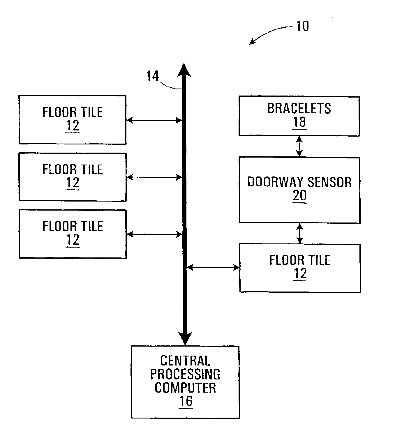
[0021]Referring to FIG. 1, a floor monitoring system generally indicated by 10 is comprised of a plurality of floor tiles 12 (only four shown), a data bus and power supply 14 and a central processing computer 16. The floor tiles 12 are mechanically interconne...


PUM


Abstract

The invention discloses a system including floor tiles for monitoring the movements of individuals across a floor surface. The system is comprised of a plurality of floor tiles electrically and mechanically interconnected. The floor tiles are monitored to determine where, when and how weight is applied to the floor tiles. The system may also comprise an identification system comprising individual transmitters and a receiver. The receiver is tied into the tile monitoring system to allow the identification of an individual on the floor surface.

Description

FIELD OF THE INVENTION[0001]The present invention relates to a system for monitoring the identity of individuals stepping onto a floor surface and movement of such individuals across the floor surface.BACKGROUND OF THE INVENTION[0002]Monitoring systems for tracking the movement of persons are known.[0003]For example, commonly owned pending Canadian Patent Application No. 2,324,967 is directed to a system for monitoring the location of an individual relative to one or more detectors. The system uses a transmitter worn by a person, which emits an identification signal which is picked up by a detector located at a monitoring station. The detectors are capable of identifying the particular individual as well as their distance from the detector. Such systems are limited in that they provide only the location of the individual relative to the detector.[0004]Floor monitoring systems are also known. The known floor monitoring systems use pressure gauges to detect when weight is placed on th...

Claims


Application Information

Patent Timeline
IPC IPC(8): G07C9/00G08B13/10G08B3/10G08B13/02G08B3/00
CPCG07C9/00103G07C9/00111G08B13/10G08B13/2462G08B3/1083Y10S323/904G07C9/27G07C9/28
Inventor POWER, MICHAEL WILLIAMATKIN, GRAHAMMAC DONALD, BRUCE
Owner VITRAK SYST
Why Eureka
Try Eureka