Device indicating movements for software

a software and software technology, applied in the field of software control means, can solve problems such as major drawbacks in the type of apparatus, and achieve the effect of not being expensive to mak

Inactive Publication Date: 2005-06-21
NICOLAS FREDERIC +2
View PDF8 Cites 112 Cited by
  • Summary
  • Abstract
  • Description
  • Claims
  • Application Information

AI Technical Summary

Benefits of technology

[0010]A second object of the invention is to propose such appara...

Problems solved by technology

That type of apparatus ...

Method used


Image

  • Device indicating movements for software
  • Device indicating movements for software
  • Device indicating movements for software

Examples


Embodiment Construction

[0024]Further scope of applicability of the present invention will become apparent from the detailed description given hereinafter. However, it should be understood that the detailed description and specific examples, while indicating preferred embodiments of the invention, are given by way of illustration only, since various changes and modifications within the spirit and scope of the invention will become apparent to those skilled in the art from this detailed description.

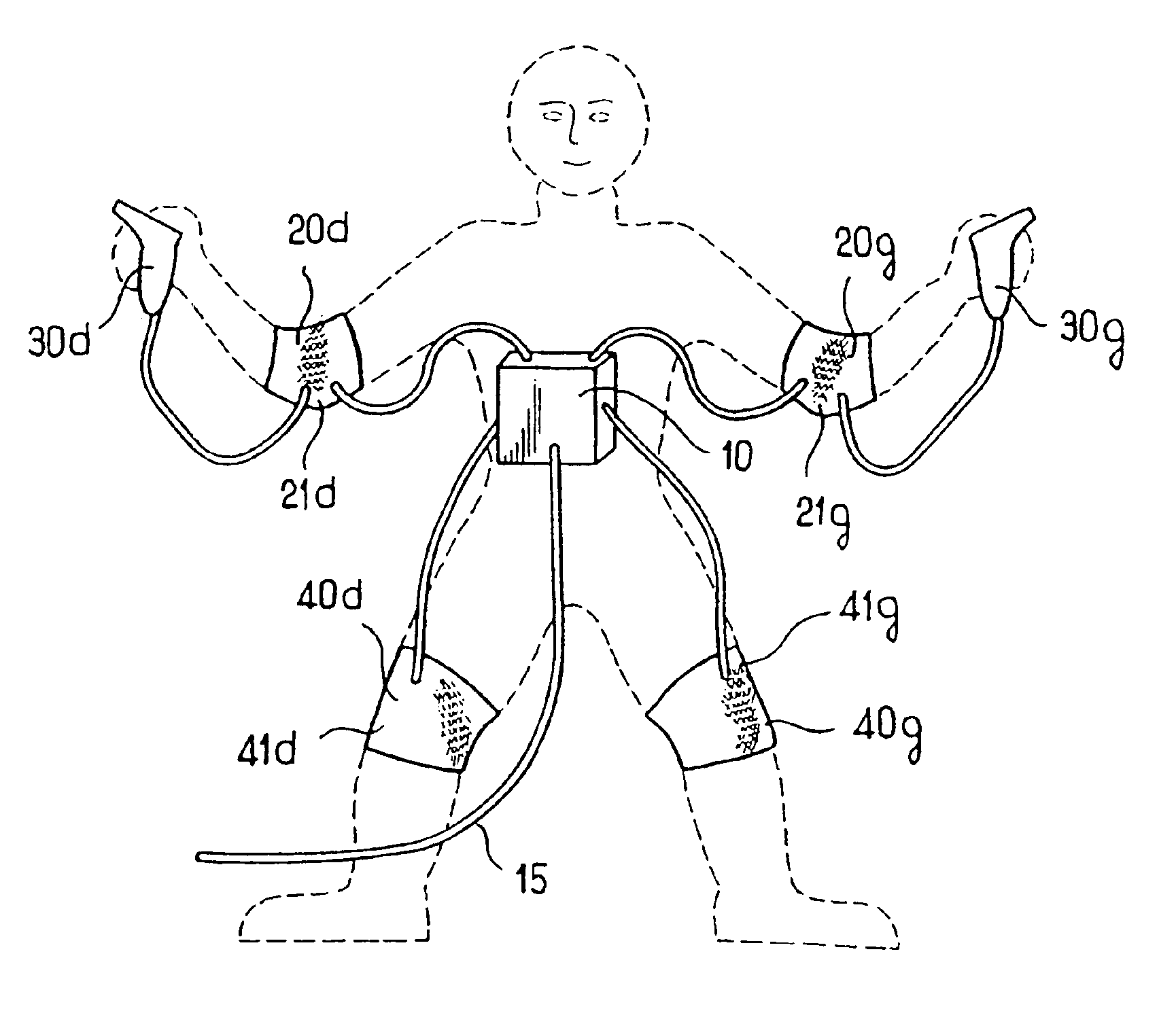
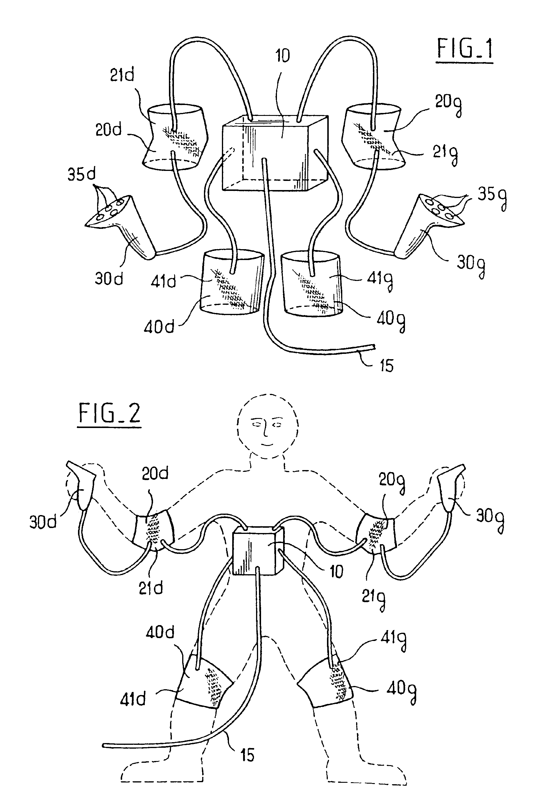
[0025]The apparatus of FIG. 1 is of star architecture, having a center constituted by a preprocessor module 10 and four branches, constituted by wire connections carrying movement sensors 20d, 20g, 40d, and 40g.

[0026]In this case, the movement sensors are responsive to knee bending 40g, 40d and to elbow bending 20g, 20d.

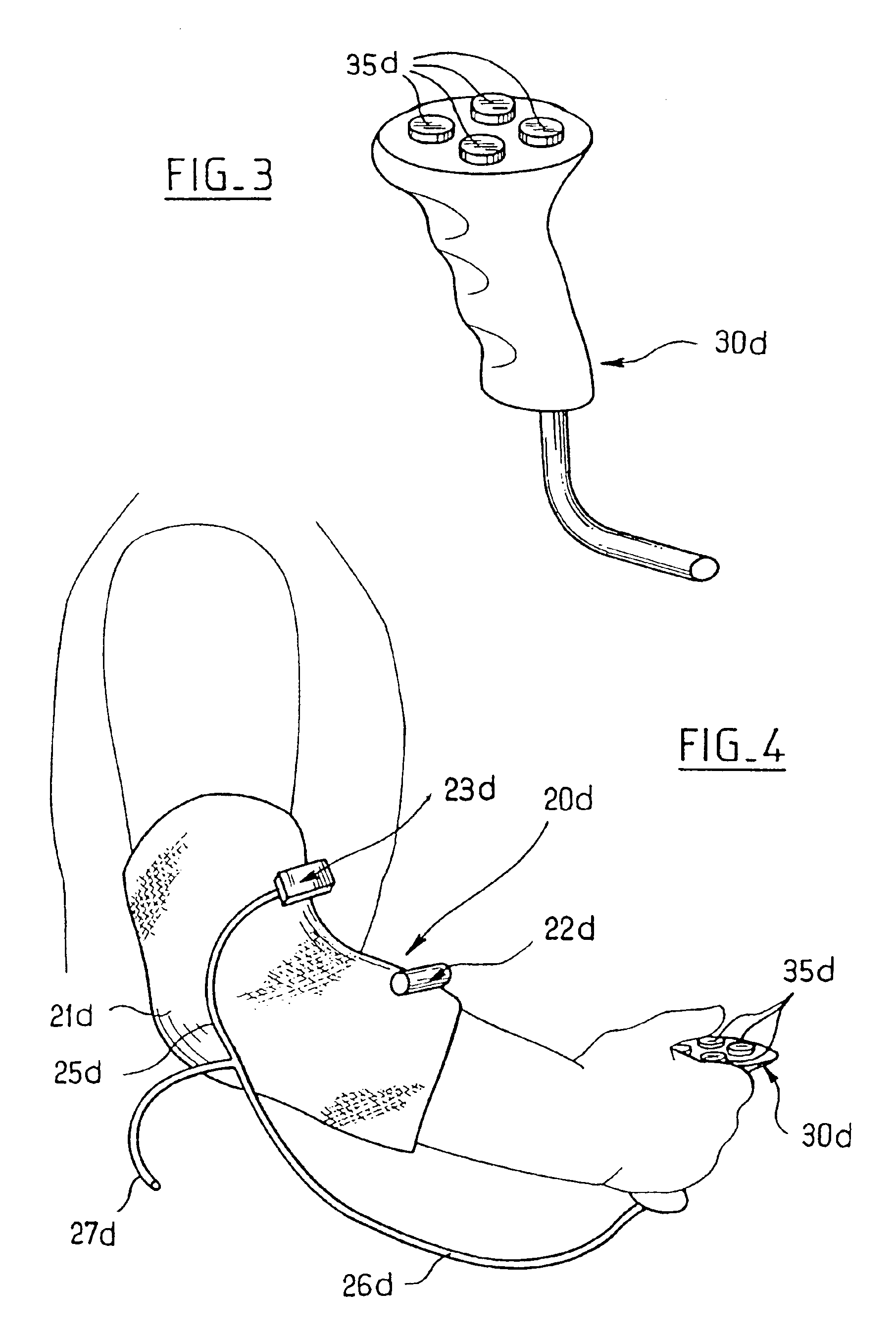
[0027]The two branches, each including an elbow-bending sensor 20d and 20g, are extended beyond the sensor to a controlling handset 30d, 30g provided with a pad of pushbuttons 35g, 35d.

[0028]As...


PUM


Abstract

A system for transforming the movements of at least one joint of a user into control signals for a computer. The system includes a sleeve for putting on over the joint and a movement sensor fixed to the sleeve for the sensor to be placed and held in the hollow of the joint. The sensor is an on/off sensor that is directly subject to the movements of the sleeve in the hollow of the joint.

Description

BACKGROUND OF THE INVENTION[0001]1. Field of the Invention[0002]The invention relates to software control means constituting sensors for sensing the movement of a part of a user's body.[0003]2. Description of the Related Art[0004]Such control means conventionally include elements which reproduce a control or guide element (a joystick, a steering wheel, control pedals) and elements which are fixed to the body of a user (e.g. the arms or the hands) and that are designed to sense movements while impeding them as little as possible.[0005]Thus, document U.S. Pat. No. 5,229,756 proposes a boxing fight simulator in which the user is fitted with elbow-bend sensors each fixed on a sleeve to measure the bend angle of an elbow and deliver an analog signal representative of said angle, which analog signal is subsequently converted into a digital signal for storing and processing.[0006]That type of apparatus suffers from a major drawback.[0007]The signal delivered by the sensor must be processed...

Claims


Application Information

Patent Timeline
IPC IPC(8): G06F1/16G06F3/00A63F13/06A63F13/00G01B21/00G06F3/01G06F3/02
CPCG06F3/011G06F1/163G06F3/017A63F13/24
Inventor NICOLAS, FREDERICHERMAND, FABIENBONNARD, JEAN
Owner NICOLAS FREDERIC
Why Eureka
Try Eureka