
System and method for positioning an implantable medical device within a body

Inactive Publication Date: 2005-06-21
MEDTRONIC INC
View PDF27 Cites 166 Cited by
  • Summary
  • Abstract
  • Description
  • Claims
  • Application Information

AI Technical Summary

Problems solved by technology

Such leads have been difficult to develop for a number of reasons.
Should lead implantation cause blood clots to develop within the left side of the heart or associated vasculature, the direction of blood flow could cause these clots to be carried to the brain, causing stroke and other tissue damage.
Thus, at present, chronic transvenous leads may not be safely implanted within the left side of the heart.
These procedures, however, involve major surgery, which may be painful and dangerous for the patient, as well as extremely costly.
The sub-xiphod approach, moreover, only permits limited access to the anterolateral surface of the left ventricle as well as to the left atrium.
One drawback to such a design, however, is that the particular shape of the curve is not ideally suited for electrically accessing the left atrium.
In addition, such a catheter is relatively complicated to manufacture because of the braid or other means that is required to reinforce the proximal section.
Finally, such a catheter does not permit introduction of a stylet to assist in the placement of the catheter into the coronary sinus.
However, this type of lead is difficult to re-position or remove, as may be necessary to improve thresholds, to increase intrinsic signal amplitudes, or to replace the lead in the case of chronic problems such as lead failure or infection.
One of the drawbacks of this particular design is the inability to re-position and / or remove the electrode as may be required for any of the reasons discussed above.
After that, the lead may not be easily re-positioned or removed.
One disadvantage of this system is that the helix is not retractable once it is deployed.

Method used


Image

  • System and method for positioning an implantable medical device within a body
  • System and method for positioning an implantable medical device within a body
  • System and method for positioning an implantable medical device within a body

Examples


Embodiment Construction

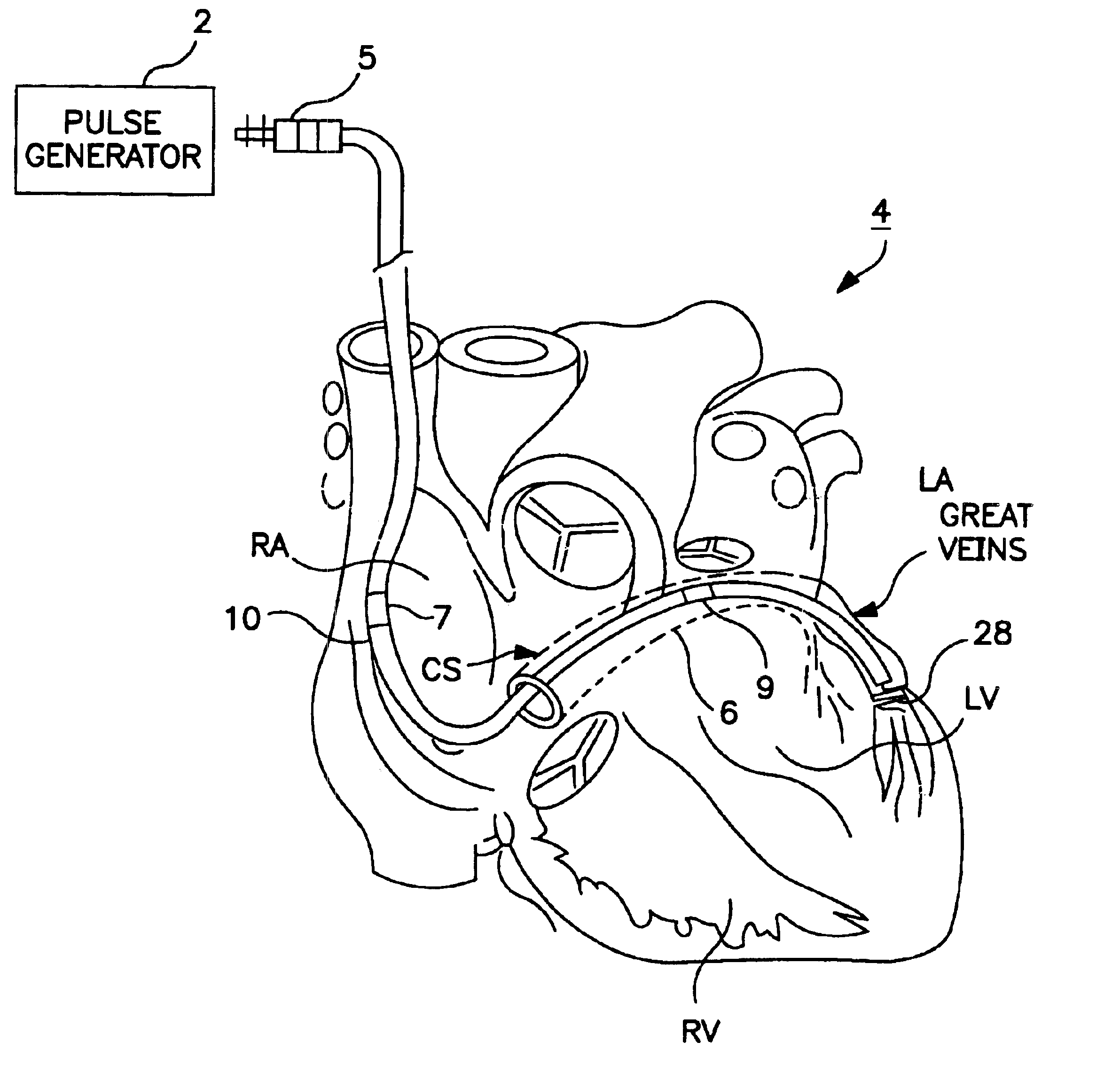
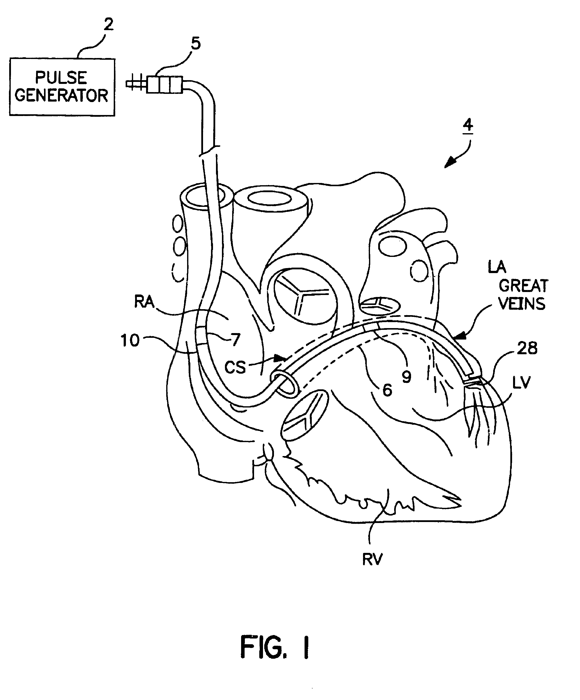
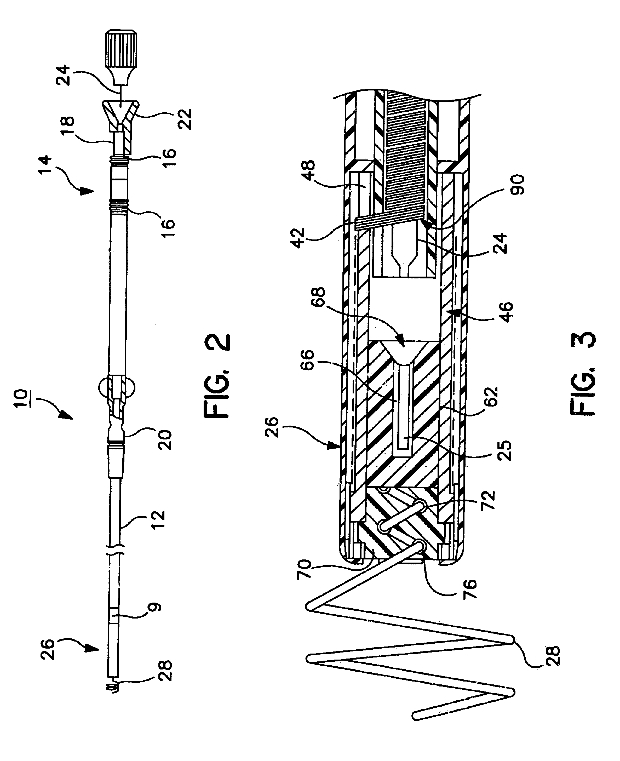
[0029]FIG. 1 is a perspective view of lead 10 according to the present invention, which is shown implanted in a heart 4. As seen in this embodiment, an implantable pulse generator 2 is coupled to a lead 10 by connector 5 as is well known in the art. Pulse generator 2 may be any model capable of sensing and stimulating two or more chambers of the heart 4 with at least one situated on the left side of heart 4. As further seen, in this embodiment, lead 10 may feature include one or more ring electrodes disposed along the lead body. In the illustrated embodiment, two ring electrodes 7 (right atrium) and 9 (left atrium) are shown. This embodiment further includes a helix 28 which extends beyond the distal end of the lead 10. Upon deployment, the helix expands and wedges within the coronary sinus, cardiac veins, or another vessel. This ensures excellent contact is maintained between the electrode 28 and the heart while also maintaining the lead 10 at the predetermined site of implant. The...


PUM


Abstract

A transvenous implantable medical device adapted for implantation in a body, and which is particularly adapted for use in a vessel such as the coronary sinus or cardiac great vein. The implantable medical device may take the form of a lead or catheter, and includes an extendable distal fixation member such as a helix. In one embodiment, the fixation member is a helix constructed of a shape memory metal or other super-elastic material. Upon deployment, the helix assumes a predetermined helix shape larger than the diameter of the lead body diameter. The helix functions to wedge or fix the lead within the vessel in a manner that does not impede the flow of blood through the vessel. The helix may be retracted for ease of repositioning and / or removal. In one embodiment of the invention, the fixation member may be advanced using a stiffening member such as a stylet. In another embodiment, the helix is coupled to a coiled conductor such that rotation of the conductor extends or retracts the helix. According to yet another aspect of the invention, a helix lumen including a flexible fluid-tight seal may be utilized to house the helix when it is in the retracted position.

Description

FIELD OF THE INVENTION[0001]This invention relates to the field of body implantable medical device systems; and in particular, to a body implantable medical device system that includes an expandable helix and that is particularly designed for implantation into a vessel of the body.BACKGROUND OF THE INVENTION[0002]Modern electrical therapeutic and diagnostic devices for the heart, such as pacemakers, cardiovertors, and defibrillators, require a reliable electrical connection between the device and a region of the heart. Typically, a medical electrical lead is used for the desired electrical connection.[0003]One type of commonly-used implantable lead is a transvenous lead generally taking the form of an elongated, substantially straight, flexible, insulated conductor. This type of lead is positioned through the venous system to attach to, and / or form an electrical connection with, the heart at the lead distal end. At the proximal end, the lead is typically connected to an implantable ...

Claims


Application Information

Patent Timeline
IPC IPC(8): A61N1/05
CPCA61N1/057A61N2001/0585
Inventor LOKHOFF, NICOLAAS M.THOMPSON, DAVID L.
Owner MEDTRONIC INC
Learn More