Cleaning device for the cleaning of a spin rotor and scraper element

Active Publication Date: 2005-06-28
RIETER INGOLSTADT SPINNEREIMASCHENBAU AG
View PDF22 Cites 10 Cited by
  • Summary
  • Abstract
  • Description
  • Claims
  • Application Information

AI Technical Summary

Benefits of technology

[0025]It is particularly advantageous in this matter, if the second control surface for the retrieval of the scraper element is designed with a domelike curvature. In this way, it can act with an O-ring, which exercises a springlike force on the scraper element in the direction of the idle position.
[0026]In order to bring a directed and defined force onto the scraper surface and at the same time design the scraper element to be economical in its manufacture, it is preferable if the scraper element is furnished with reinforcing ribs.
[0027]Plastic material, in particular polyamides, is a good material for the scraper element. In order to procure a scraper element

Problems solved by technology

Further, it is within this purpose, that during the cleaning of the spin rotor the least possible force is to be exercised against the roto

Method used


Image

  • Cleaning device for the cleaning of a spin rotor and scraper element
  • Cleaning device for the cleaning of a spin rotor and scraper element
  • Cleaning device for the cleaning of a spin rotor and scraper element

Examples


Example

[0037]Reference will now be made in detail to the presently preferred embodiments of the invention, one or more examples of which are shown in the figures. Each example is provided to explain the invention, and not as a limitation of the invention. In fact, features illustrated or described as part of one embodiment can be used with another embodiment to yield still a further embodiment. It is intended that the present invention cover such modifications and variations.

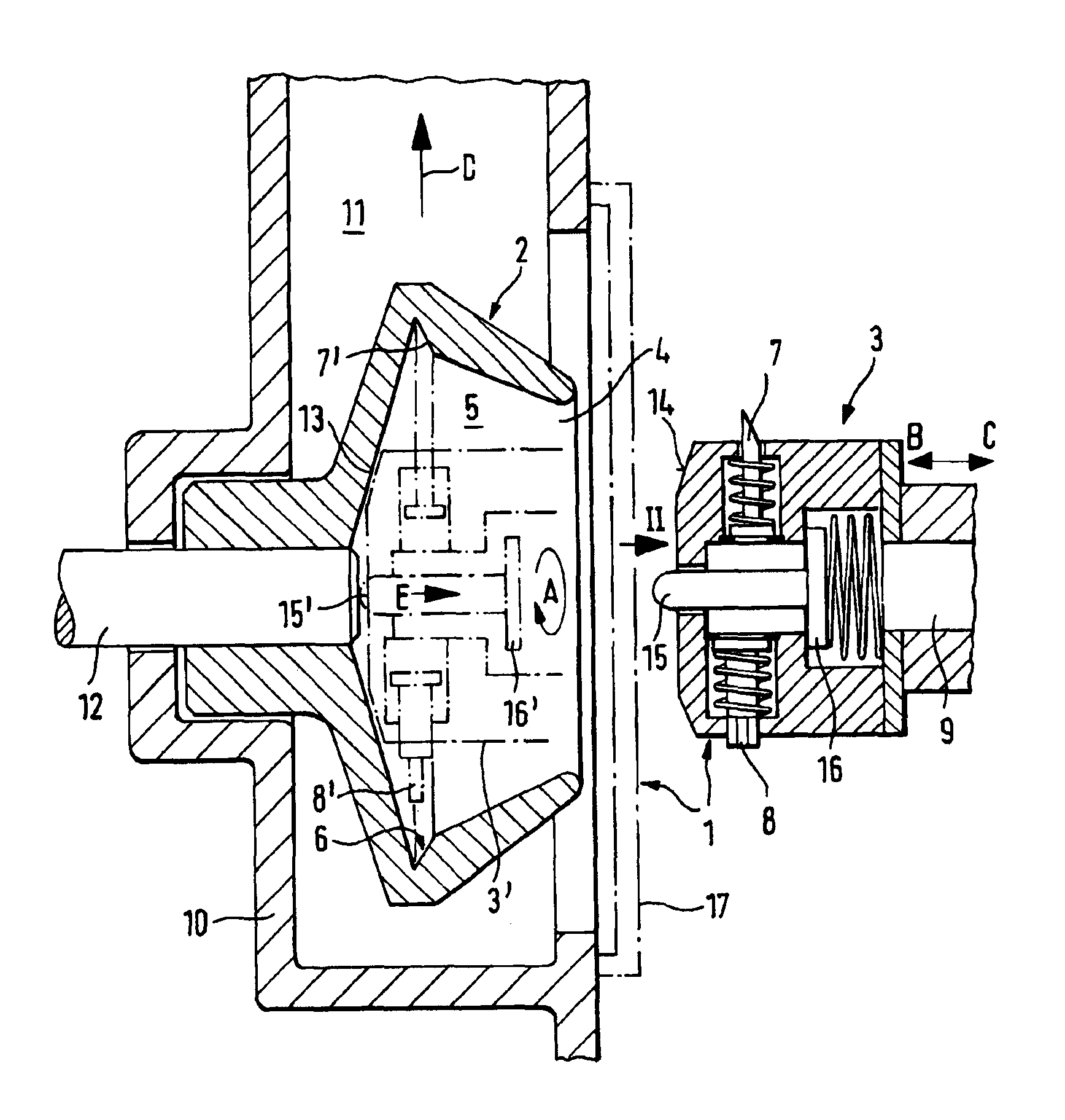
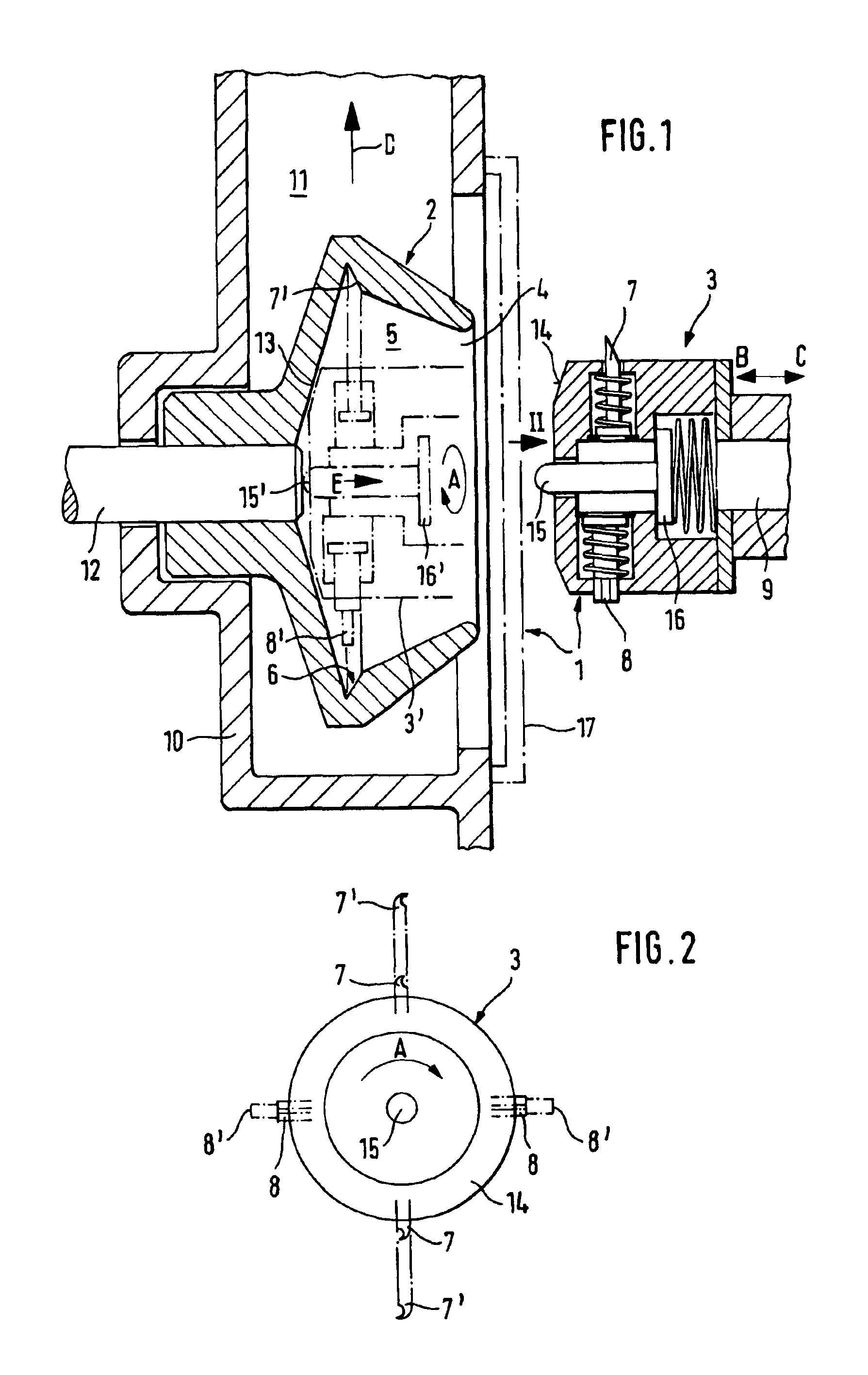
[0038]The apparatus 1 depicted in FIGS. 1 and 2, serves for the cleaning of a motionless spin rotor 2, which, preferentially is held still by the action of a (not shown) braking means. Normally what is involved here is a spin rotor 2 having a small diameter, preferably less than 30 mm, as is conventionally used today.

[0039]The apparatus 1 contains a cleaning head 3, which, advantageously is a component of a (not shown) traveling service cart. This cleaning head 3 is, in case of maintenance attention, displaceable in th...


PUM

PropertyMeasurementUnit
Angleaaaaaaaaaa
Angleaaaaaaaaaa
Forceaaaaaaaaaa

Abstract

The invention concerns a cleaning apparatus for the cleaning of a spin rotor of a spinning station leaning head which can be insertably presented to the spin rotor and on which cleaning head are placed at least two scraper elements. In accord with the invention, the at least two scraper elements are pneumatically extendable, wherein the position of the two scraper elements are so secured on the outer circumference of the cleaning head, that the sum of the contact forces which are exerted from the scraper element in the radial direction onto the rotor is zero, or practically zero.

Description

BACKGROUND OF THE INVENTION[0001]The invention concerns a cleaning apparatus for the cleaning of a spin rotor in a rotor spinning machine, with a cleaning head which can be insertably presented to a spin rotor on which at least two scraper elements are placed and the invention also concerns a scraper element corresponding thereto.[0002]U.S. Pat. No. 4,339,914 discloses a cleaning apparatus which is mounted on a service cart which is capable of movement, whereby the apparatus can be presented to a spin rotor for the cleaning of the same. On the cleaning head of the cleaning apparatus, a scraper is placed, which, by means of a pneumatic cylinder can cleaningly enter into the rotor groove of the spin rotor. For the cleaning of the rotor groove, the spin rotor is caused to rotate. In order to achieve a sufficient cleaning effect, the scraper must be subjected to pressure to achieve a correspondingly sufficient force of cleaning contact. On this account, the spin rotor receives an asymme...

Claims


Application Information

Patent Timeline
IPC IPC(8): D01H4/00D01H4/24
CPCD01H4/24
Inventor STEPHAN, ADALBERTLIMMER, RALFSTAHLECKER, GERD
Owner RIETER INGOLSTADT SPINNEREIMASCHENBAU AG
Why Eureka
Try Eureka