Coupling device

a technology of coupling device and transfer rail, which is applied in the direction of rod connection, magnetic body, forging press, etc., can solve the problems of laborious and time-consuming physical removal of the transfer rail, increased manufacturing process cost, and increased failure risk, and achieves easy transfer of load, convenient operation, and light weight

Inactive Publication Date: 2005-06-28
LINEAR TRANSFER SYST
View PDF21 Cites 4 Cited by
  • Summary
  • Abstract
  • Description
  • Claims
  • Application Information

AI Technical Summary

Benefits of technology

[0008]The invention therefore provides a coupling device that may be used to releaseably secure together two objects, such as two sections of a transfer rail utilized in a linear transfer system. The invention provides such a coupling device that is mechanically efficient, that operates quickly and without significant operator intervention, that is structurally sound to provide a mechanism that readily transfers load between adjacent parts, and that is of a relatively light weight.

Problems solved by technology

In either instance the physical removal of the transfer rail can be a laborious and time consuming procedure adding expense to the manufacturing process by way of increased operator time and by increasing the down time of the press.
Unfortunately, such transfer rails have generally met with limited success as the systems utilized to fasten rail sections together end to end have tended to be either no more convenient than simply removing the entire rail, or mechanically complex thereby making them more costly and more prone to failure.
Furthermore, such prior connecting systems have tended to present a weakness in the structural integrity of the rail at the juncture of adjacent sections.
Such components are typically undesirable on account of the increased weight that they add to the transfer rail.

Method used


Image

  • Coupling device
  • Coupling device
  • Coupling device

Examples


Embodiment Construction

[0021]The present invention may be embodied in a number of different forms. However, the specification and drawings that follow describe and disclose only some of the specific forms of the invention and are not intended to limit the scope of the invention as defined in the claims that follow herein.

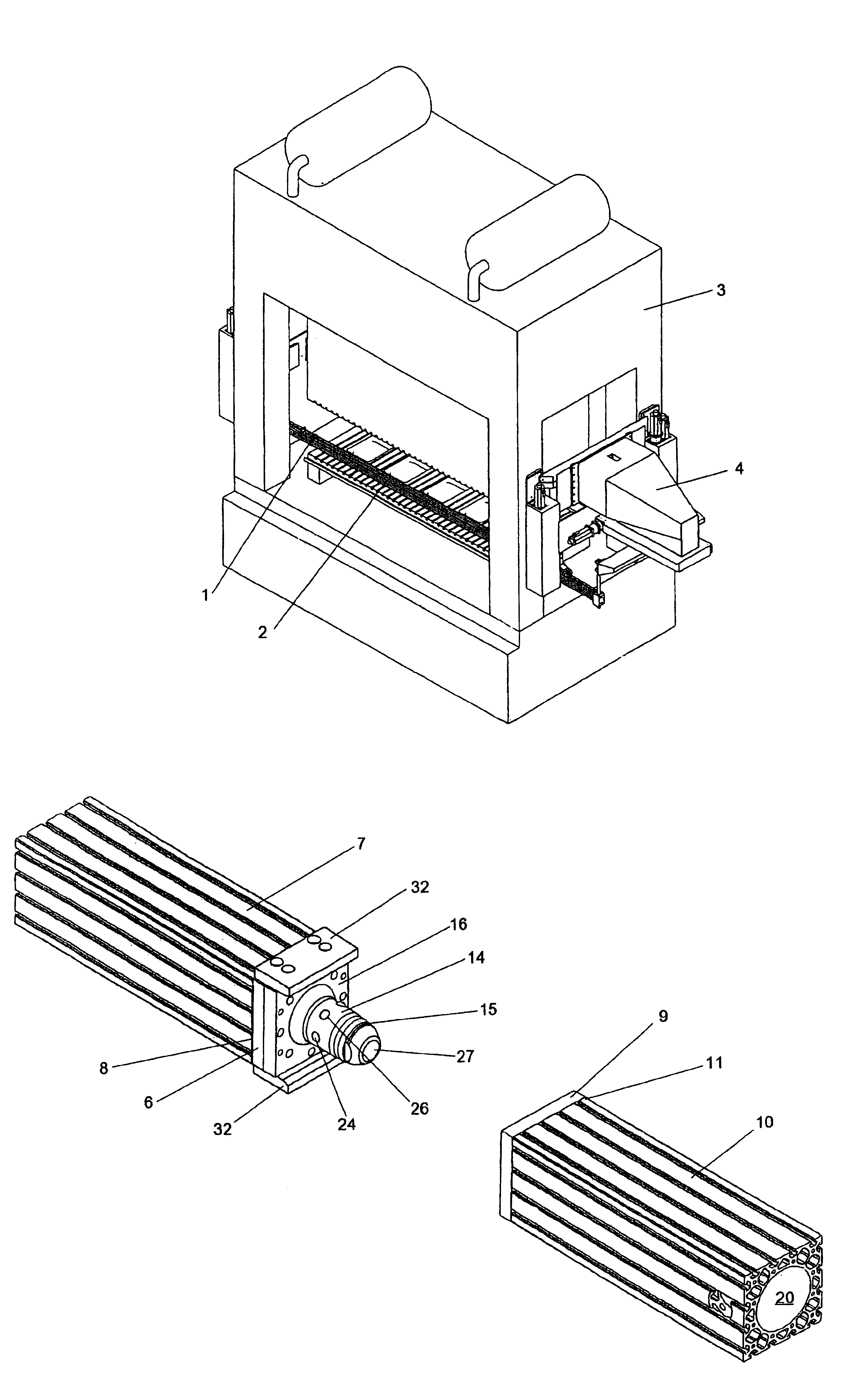
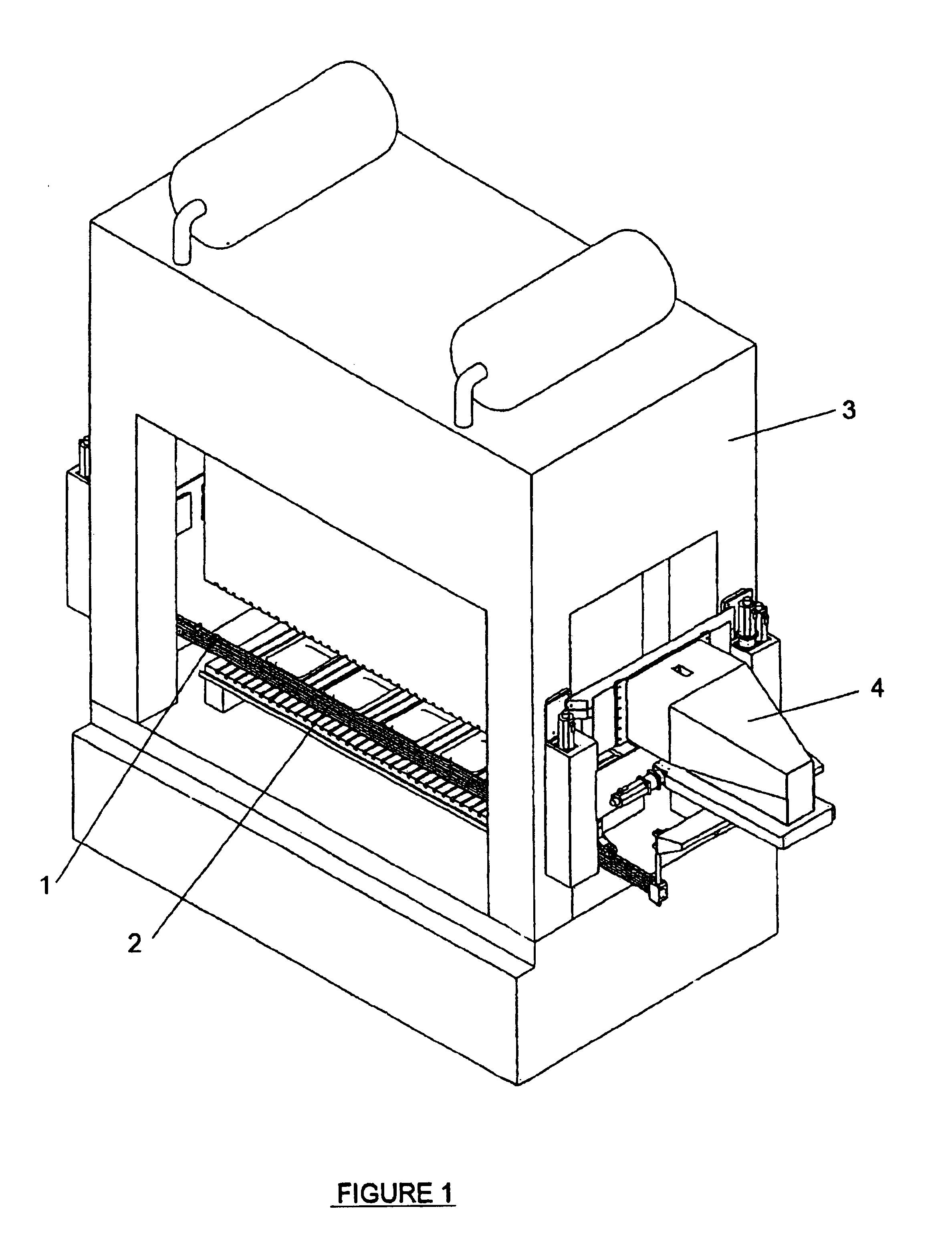
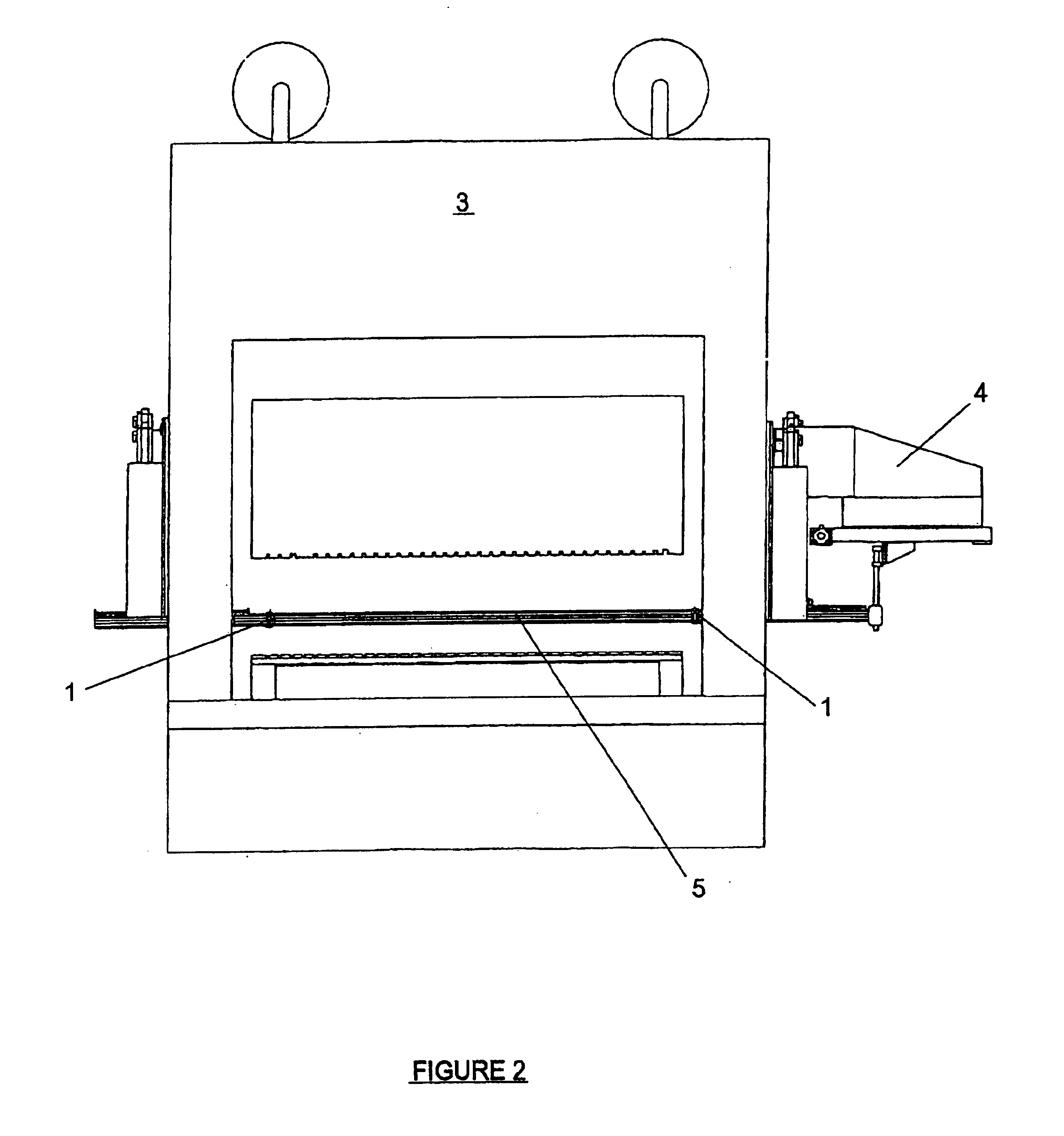
[0022]The coupling device in accordance with a preferred embodiment of the present invention is noted generally in the attached drawings by reference numeral 1. While it will be appreciated that coupling device 1 may be utilized to secure together a variety of different objects, for illustration purposes in the attached drawings coupling device 1 has been shown as it would typically be used to secure together the ends of two sections of a transfer rail 2.

[0023]FIGS. 1 and 2 generally depict a press 3 having mounted thereon a linear transfer system 4 that utilizes a pair of transfer rails 2 (only one of which is shown in the drawings) in order to assist in the movement of workpieces betwee...


PUM

PropertyMeasurementUnit
sizeaaaaaaaaaa
bending momentsaaaaaaaaaa
circumferenceaaaaaaaaaa

Abstract

A coupling device for releaseably securing together two objects. The coupling device comprises a first housing securable to a first object, a second housing securable to a second object, and an actuator secured to the first housing. The second housing has a hollow bore therein. At least part of the actuator is releaseably receivable within the hollow bore of the second housing. The actuator has an activated and a deactivated configuration. When in its activated configuration at least a portion of the periphery of the actuator is in an expanded state such that when situated within the hollow bore of the second housing the expanded periphery of the actuator releaseably secures the first housing to the second housing. When the actuator is in its deactivated configuration the periphery of the actuator in a retracted state permitting separation and relative movement between the first and second housings. The actuator and the first and second housings receive and dissipate bending moments applied thereto across the first and second objects to resist flexure therebetween.

Description

[0001]This application claims priority from Canadian Patent Application 2,345,860 filed May 1, 2001.FIELD OF THE INVENTION[0002]This invention relates to coupling devices, and in one embodiment hydraulic couplings that may be used to releaseably secure together adjacent ends of transfer rails in a press transfer system.BACKGROUND OF THE INVENTION[0003]The manufacturing industry, and in particular the metal fabrication and stamping industries, commonly utilize automated systems that allow a workpiece to be conveyed or transferred between equally spaced workstations where particular operations are carried out upon the workpiece. For example, many metal parts on automobiles and appliances are formed by means of a stamping procedure wherein a series of separate dies are situated on a series of aligned and equally spaced workstations within a press bed such that a workpiece will be stamped between a pair of dies upon each stroke of the press. Automated transfer systems are typically empl...

Claims


Application Information

Patent Timeline
Patent Type & Authority Patents(United States)
IPC IPC(8): F16B21/16F16B21/00F16B7/04
CPCF16B7/042F16B21/165Y10T403/557Y10T403/592
Inventor CHILDS, MONTGOMERY W.BROADLEY, MALCOLMBROWN, RYAN
Owner LINEAR TRANSFER SYST
Why Eureka
Try Eureka