Portable power jack device

a power jack and portability technology, applied in the field of jacks, can solve the problems of injuring hands or fingers in operating the jack, distinctively different structure, and knowing the hassle and potential for serious injury involved in the operation of the jack, and achieves the effects of low manufacturing cost, low price of sale, and easy and efficient manufacturing and marketing

Inactive Publication Date: 2005-06-28
MILLER TERRY R +1
View PDF5 Cites 30 Cited by
  • Summary
  • Abstract
  • Description
  • Claims
  • Application Information

AI Technical Summary

Benefits of technology

[0021]It is another object of the present invention to provide a new and improved portable power jack device that may be easily and efficiently manufactured and marketed.
[0022]An even further object of the present invention is to provide a new and improved portable powerjack device that has a low cost of manufacture with regard to both materials and labo

Problems solved by technology

Anyone who has changed a flat tire knows the hassle and potential for serious injury involved with jacking up a car along the side of the road.
There can be trouble in getting the jack assembled and in place under the vehicle's frame or axle, as well as the possibility of injuring the hands or fingers in operating the jack.
Then there is the safety concern of the vehicle falling off the jack while the tire is being changed.
For example, the Levine '230 patent does not disclose a unit positioned on a flat stable platform for providing a safer working environment.
However, although the Huang '138 patent, like the Levine '230 patent, discloses a device that is similar in function, it is distinctively different in structure from that of the present invention and in particular does not disclose a unit positioned on a flat stable platform for providing a safer working environment.
However, the Yoshida '964 patent discloses a device that is different in structure from that the Levine '230 patent, and does not disclose a contained port

Method used


Image

  • Portable power jack device
  • Portable power jack device
  • Portable power jack device

Examples


Embodiment Construction

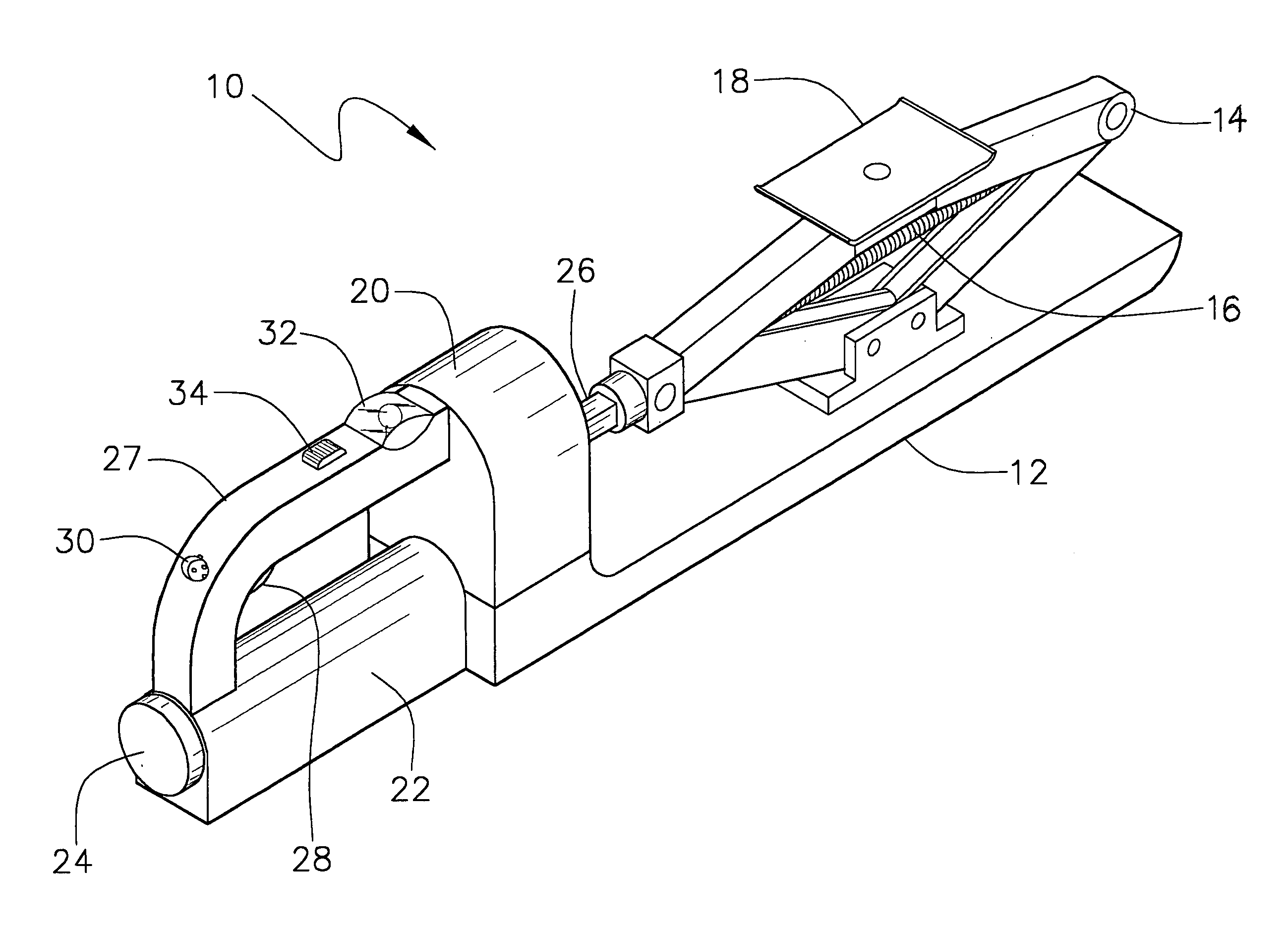
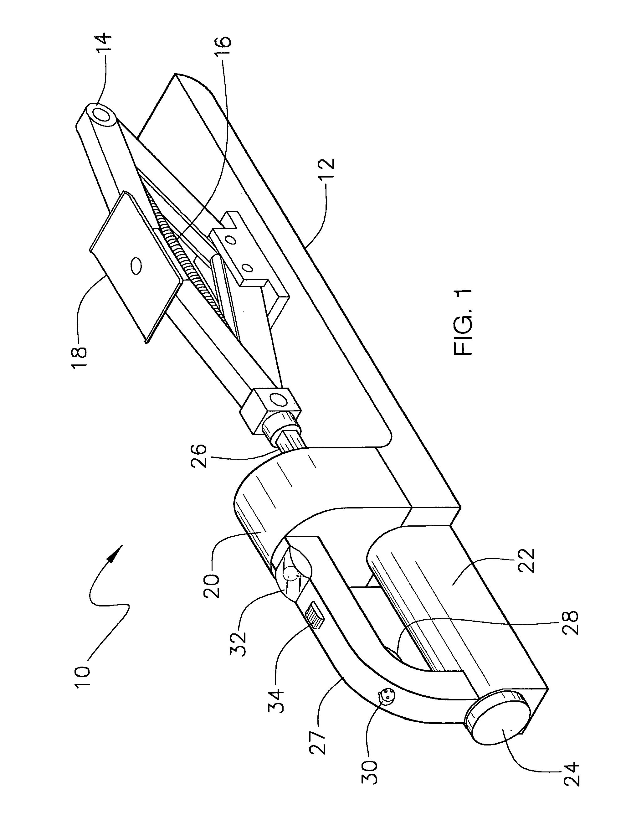
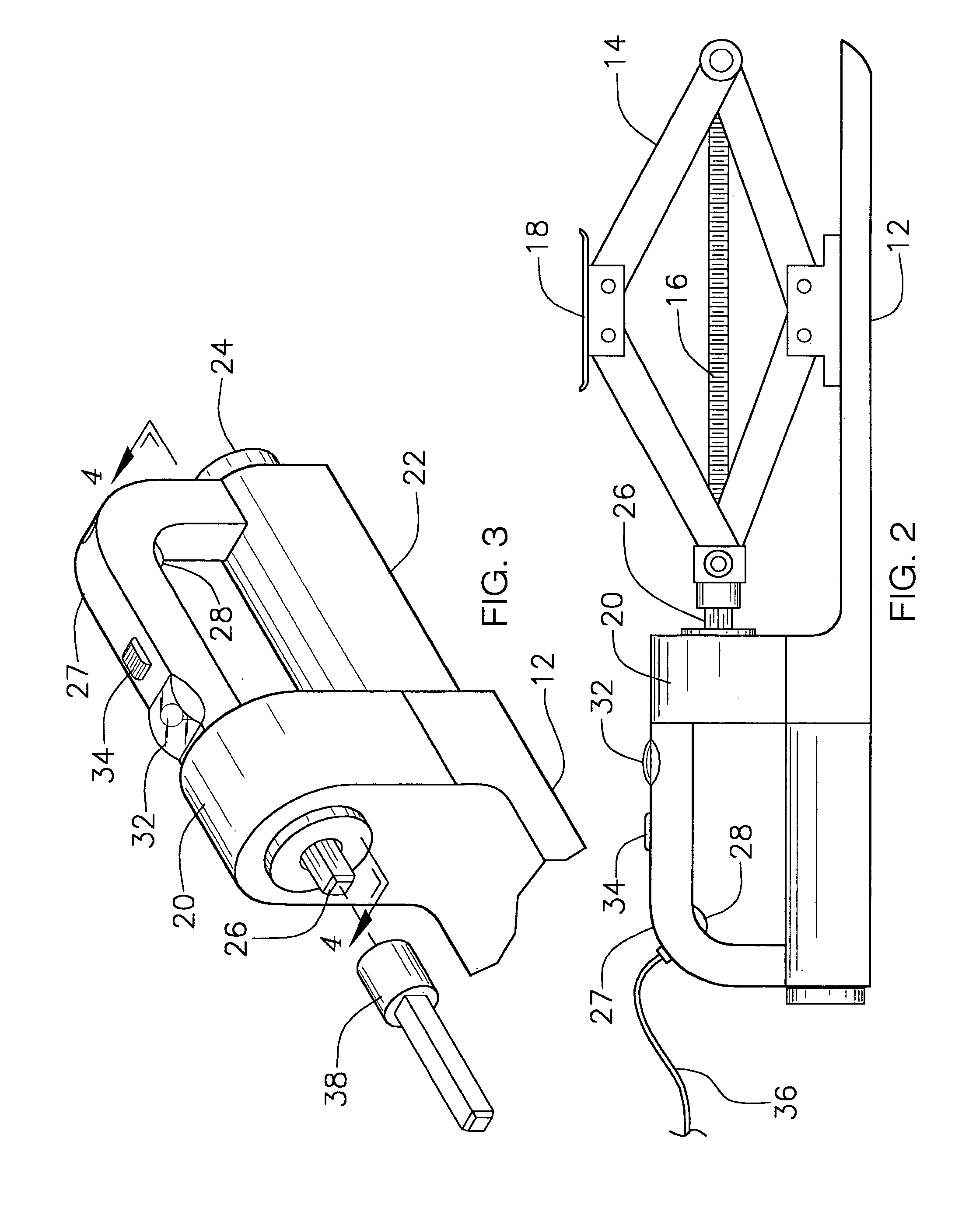
[0032]Referring now to the drawings, and particularly to FIGS. 1–5, a preferred embodiment of the portable power jack device of the present invention is shown and generally designated by the reference numeral 10.

[0033]In FIGS. 1, 2, and 3 the new and improved portable power jack device 10 of the preferred embodiment of the present invention, which provides a fast, safe, and convenient device for raising and lowering an object, is illustrated and described in an overall perspective view, a side view, and a perspective view of the power drive end of the device, respectively. More particularly, the portable power jack device 10 comprises a solid metal base plate 12, having a flat stable bottom surface for contact with the ground, a scissor-jack 14 mounted at one end and a motor / gear assembly, enclosed in a housing 20, mounted at the opposite end with the drive shaft 26 of the gear assembly being coupled by coupler 38 means to the input coupler of said scissor-jack 14. The scissor-jack ...


PUM


Abstract

A battery driven reversible motor and speed reduction gear assembly coupled to a worm-screw scissor jack, all mounted on a flat, stable platform (base plate) for use in raising and lowering the corner of a vehicle. The device can be powered from a rechargeable battery pack or from the vehicle's battery. A controller unit extended by means of a cable is used to raise and lower the vehicle while the user stands out-of-the-way in safe location. The device also has a light for illuminating the work area for nighttime application. In use, the lift plate on top of the scissor-jack is placed under the frame or axle of the vehicle close to the flat tire and the power switch is turned ON. The user then walks away from the vehicle, with the controller unit in his/her hand, to a safe distance. The UP button on the controller unit is pressed to enable the motor and gear drive so that the drive shaft, which is coupled to the worn-screw of the scissor-jack, turns slowly lifting the corner of the vehicle up until the flat tire is off the ground. This process is reversed to lower the vehicle once the flat tire has been changed.

Description

BACKGROUND OF THE INVENTION[0001]1. Field of the Invention[0002]The present invention relates to a jack for use in connection with raising and lowering a vehicle. The portable power jack device has particular utility in connection with quickly and safely raising a vehicle wheel off the ground to change a flat tire.[0003]2. Description of the Prior Art[0004]Anyone who has changed a flat tire knows the hassle and potential for serious injury involved with jacking up a car along the side of the road. There can be trouble in getting the jack assembled and in place under the vehicle's frame or axle, as well as the possibility of injuring the hands or fingers in operating the jack. Then there is the safety concern of the vehicle falling off the jack while the tire is being changed. Power driven jacks are desirable since they allow the person changing the tire to stand out-of-the-way of the vehicle while raising the tire off the ground and require very little physical exertion in raising o...

Claims


Application Information

Patent Timeline
IPC IPC(8): B66F3/18B66F3/00B66F3/12B66F3/44
CPCB66F3/12B66F3/44Y10S254/03Y10S254/02Y10S254/01
Inventor MILLER, TERRY R.MILLER, PATRICIA N.
Owner MILLER TERRY R
Why Eureka
Try Eureka