Honing method and honing apparatus

Active Publication Date: 2005-06-28
NISSAN MOTOR CO LTD
View PDF14 Cites 6 Cited by
  • Summary
  • Abstract
  • Description
  • Claims
  • Application Information

AI Technical Summary

Benefits of technology

[0011]It is, therefore, an object of the present invention to allow the shape of a workpiece to be s

Problems solved by technology

If the subsequent finishing honing is carried out continuously to the coarse honing while the cylinder bore 1 is being deformed as shown in FIG. 9A, it becomes disadvantageously difficult to h

Method used


Image

  • Honing method and honing apparatus
  • Honing method and honing apparatus
  • Honing method and honing apparatus

Examples


Embodiment Construction

[0031]The embodiment of the present invention will be described hereinafter with reference to the drawings.

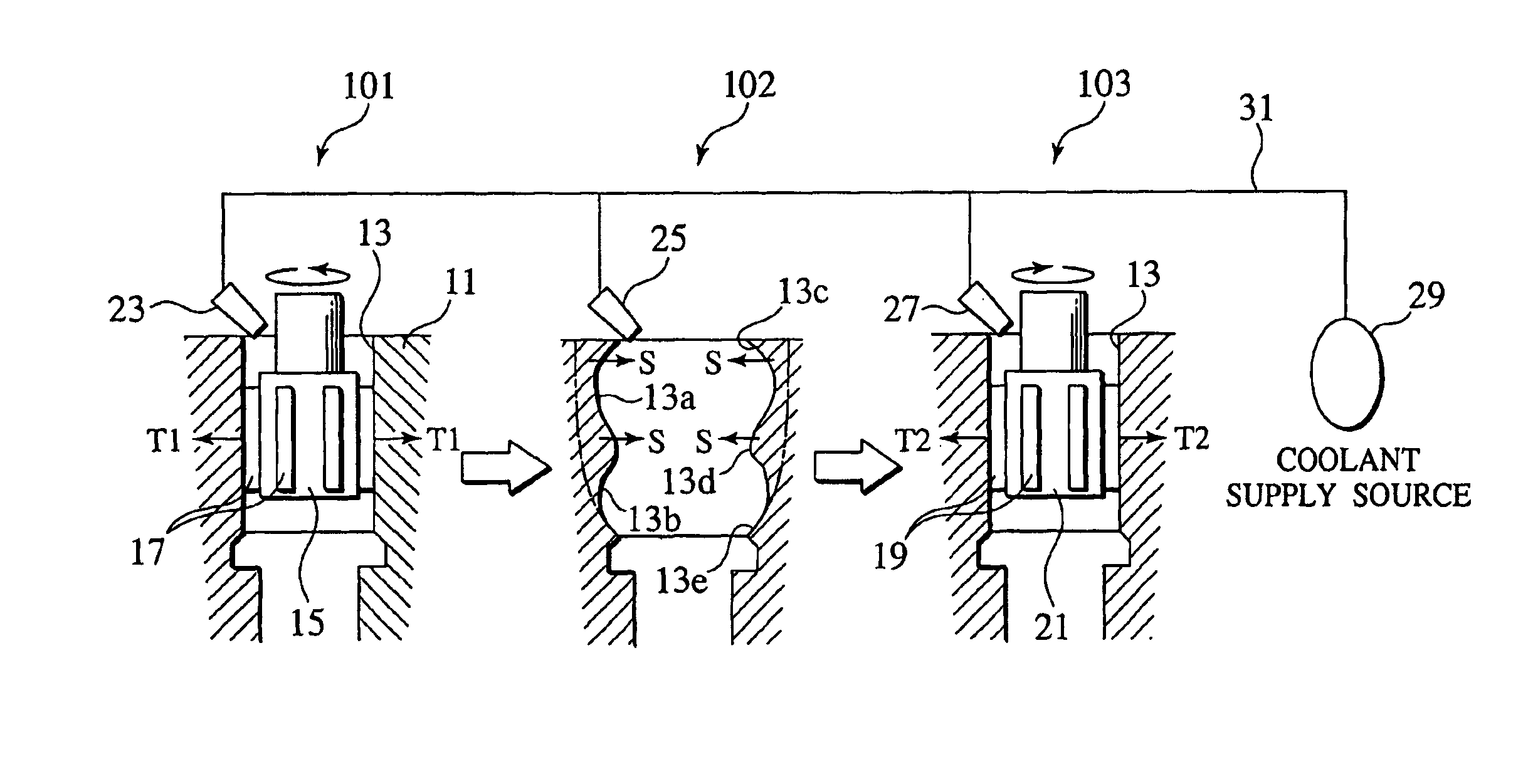
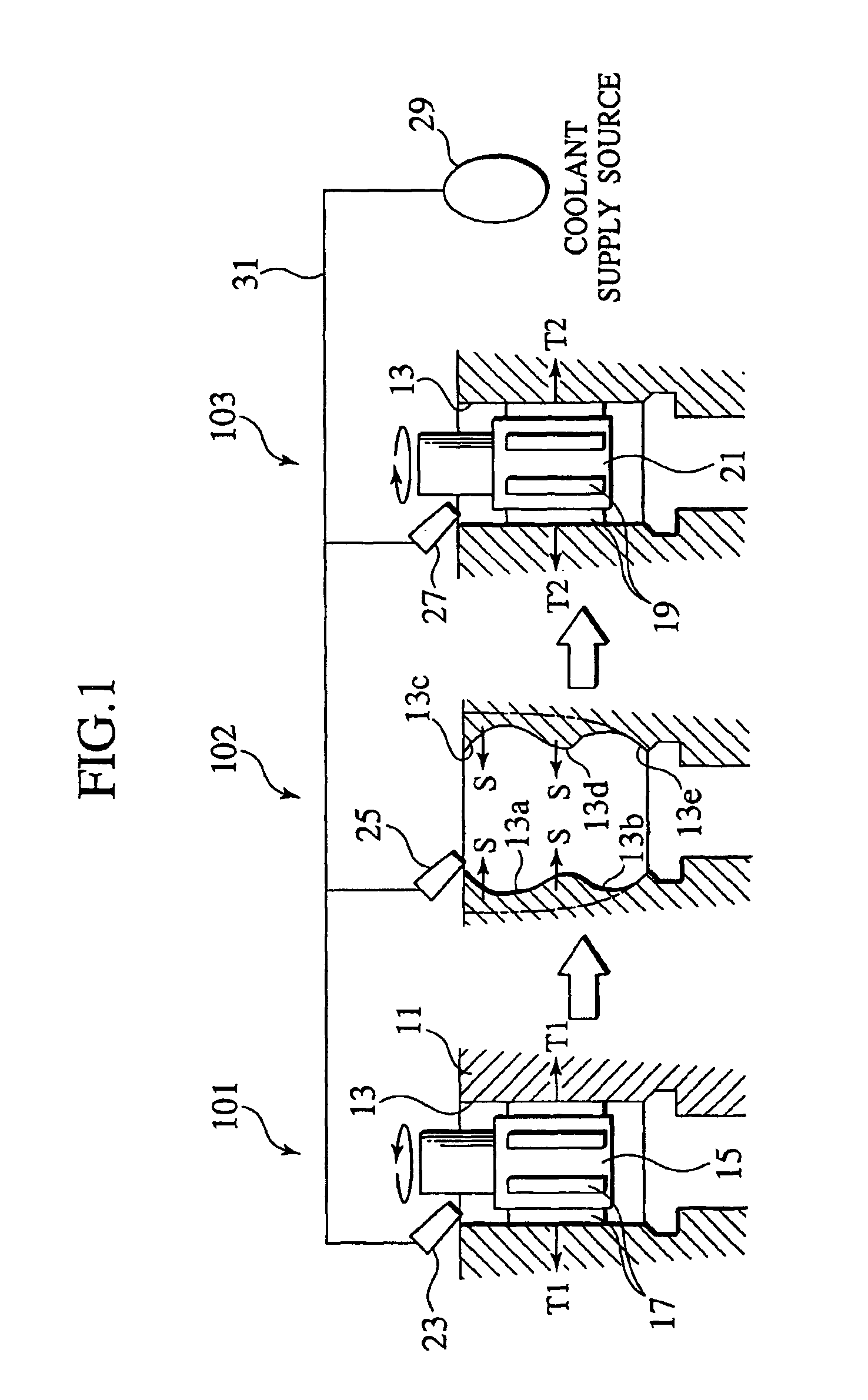
[0032]FIG. 1 shows a honing method in one embodiment according to the present invention. In FIG. 1, reference symbol 101 denotes a coarse honing step section for the honing method, and 103 denotes a finishing honing step section therefore. Further, between the coarse honing step section 101 and the finishing honing step section 103, an idling step section 102 for leaving a workpiece as it is for a predetermined time (“left-alone time” or “leaving time”) is provided. These step sections are set on the same machining line (working line). An engine cylinder block 11 having a cylindrical inner surface is carried on this line as a workpiece in the order of the coarse honing step section 101, the idling step section 102 and the finishing honing step section 103.

[0033]As shown in the coarse honing step of FIG. 1, a honing head 15 is inserted into the cylinder bore 13 of the cylinder b...


PUM

PropertyMeasurementUnit
Timeaaaaaaaaaa
Timeaaaaaaaaaa
Temperatureaaaaaaaaaa

Abstract

In a coarse honing step in a section (101), a honing head (15) provided with coarse honing hones (17) is inserted into a cylinder bore (13) of a cylinder block (11), the honing head 15 is rotated while axially moving it, and the inner peripheral surface of the cylinder bore (13) is thereby ground. In the next idling step in a section (102), the cylinder block (11) is left as it is for (60) seconds to generate a springback (S). In a subsequent finishing honing step in a section (103), a honing head (21) provided with finishing honing hones (19) is inserted into the cylinder bore (13), the honing head (21) is rotated in a reverse direction to a rotational direction in the coarse honing step while axially moving it, and the inner peripheral surface of the cylinder bore (13) is thereby ground. Further, a coolant is supplied to the sections of the coarse honing step, the idling step, and the finishing honing step from coolant nozzles (23), (25), and (27), respectively, using a common coolant supply source (29).

Description

BACKGROUND OF THE INVENTION[0001]1. Field of the Invention[0002]The present invention relates to a honing method and a honing apparatus for grinding the inner surface of a workpiece carried on a machining line by rotating a honing head having hones relative to the workpiece while axially moving the honing head.[0003]2. Description of the Related Art[0004]A workpiece having a cylindrical inner surface, e.g., the cylinder bore of a cylinder block is an important region that determines engine performance. For this reason, the cylinder bore is required to have high shape accuracy and good surface profile. As the shape accuracy, it is required to make the roundness and cylindricity of the cylinder bore as high as possible in order to reduce piston sliding resistance. As for the surface profile, it is desirable to ensure enough roughness to hold oil and expose graphite, serving as a fixed lubricant, to the surface of the bore as much as possible in order to decrease the seizure (scuff) of...

Claims


Application Information

Patent Timeline
IPC IPC(8): B24B33/02B24B33/00
CPCB24B33/02
Inventor SUZUKI, KIYOHISAIIYA, TAKASHI
Owner NISSAN MOTOR CO LTD
Why Eureka
Try Eureka