Micro capsule robot

a micro capsule and robot technology, applied in the field of micro capsule robots, can solve the problems of large influence on pain and lesion decision, patient may feel pain and unpleasant feeling, and doctor cannot stop the movement of the micro capsul

Inactive Publication Date: 2005-06-28
KOREA INST OF SCI & TECH
View PDF6 Cites 102 Cited by
  • Summary
  • Abstract
  • Description
  • Claims
  • Application Information

AI Technical Summary

Benefits of technology

[0009]Therefore, an object of the present invention is to provide a micro capsule robot which is able to control movements of itself in an organ, by delaying or stopping.

Problems solved by technology

However, in case of a colonscopy, a patient may feel pain and unpleasant feeling.
Because the colon is bent with large angle, and therefore, the pain and lesion decision are greatly affected by experience and skill of the doctor.
However, these methods are indirect because the doctor can not directly see an affected part to care for the part and can not perform a biopsy.
However, the micro capsule having the radio camera system is moved according to peristalsis of organs, and therefore, the doctor can not stop the movements of the micro capsule even in case that the doctor wishes to examine a certain location.

Method used


Image

  • Micro capsule robot
  • Micro capsule robot
  • Micro capsule robot

Examples


first embodiment

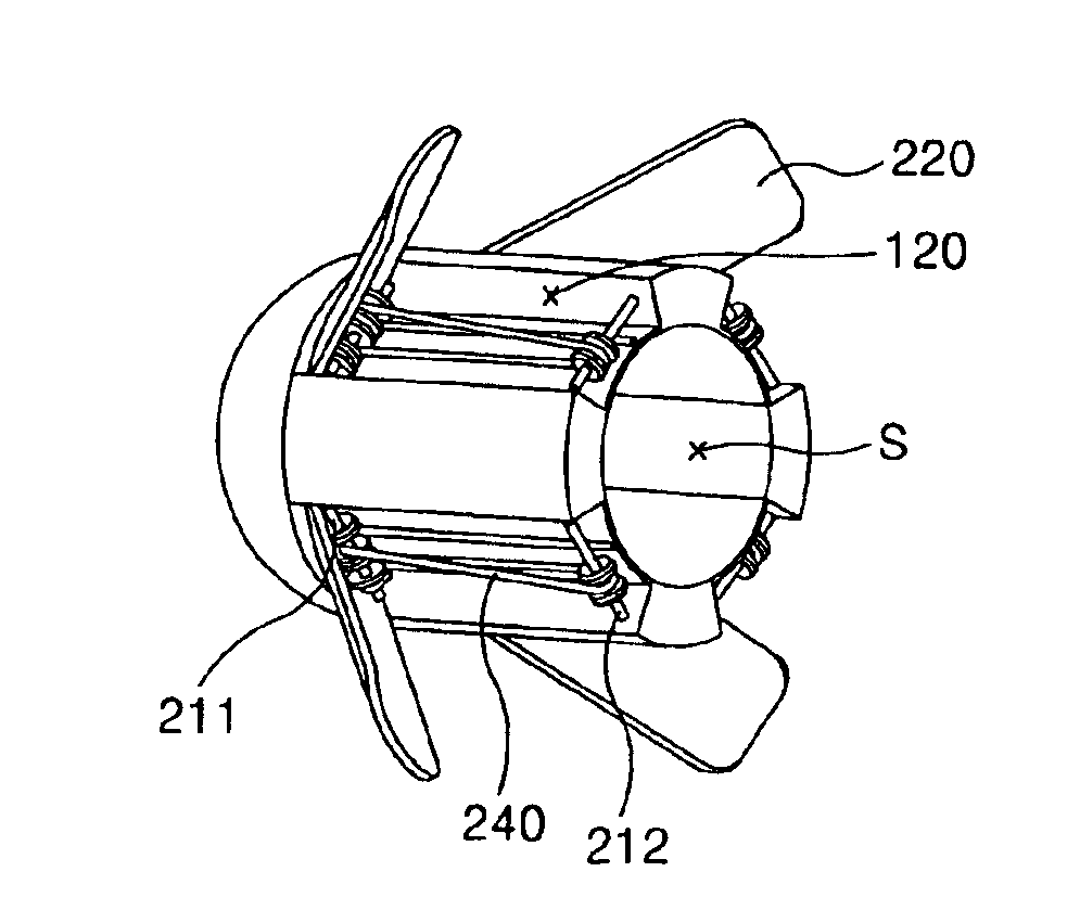
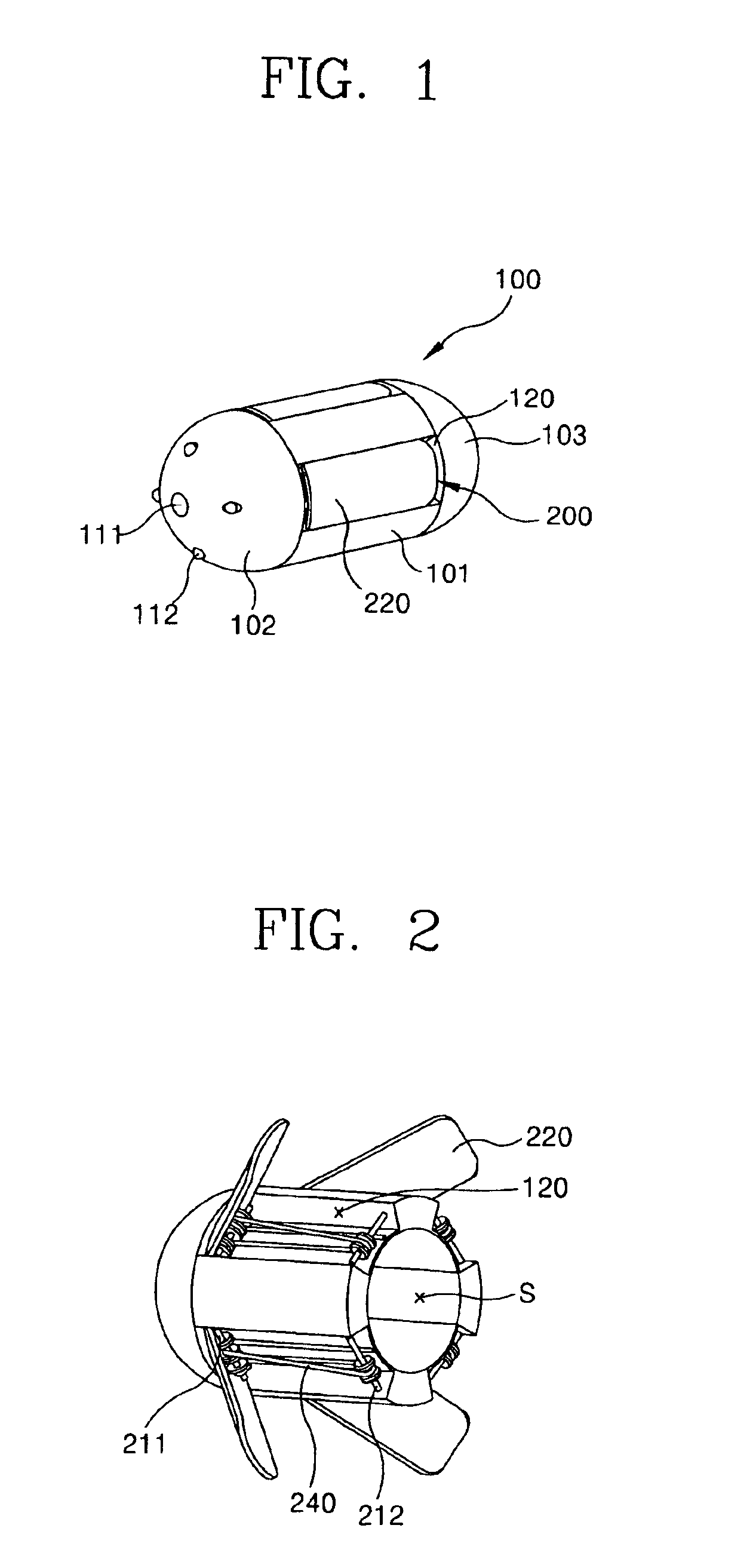
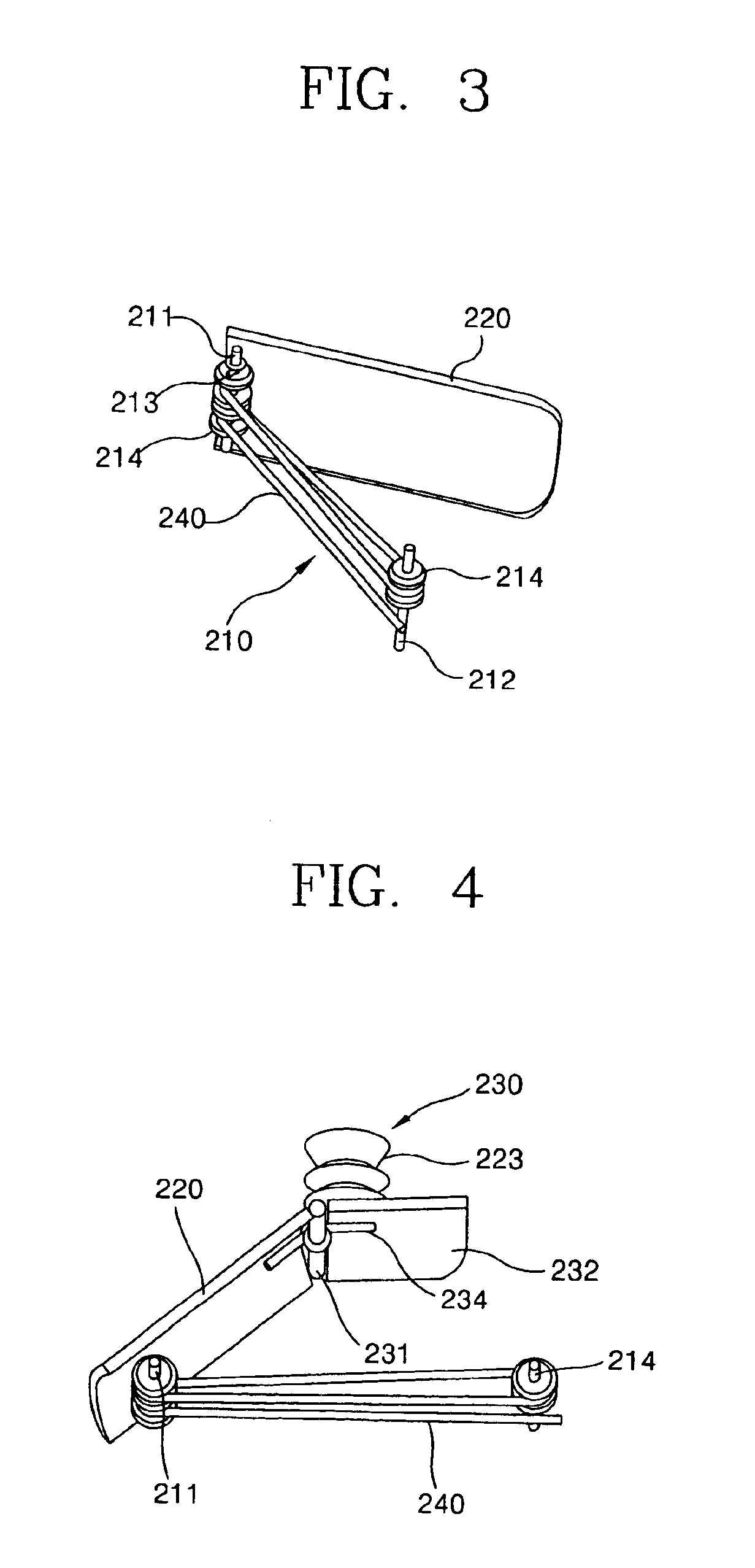
[0032]FIG. 1 is a perspective view showing the micro capsule robot according to the present invention, FIG. 2 is a perspective view showing a status that wings of the micro capsule are unfolded, FIG. 3 is a perspective view showing driving principle of the wings on the micro capsule robot shown in FIG. 1, FIG. 4 is a perspective view showing a case that an suction unit is additionally installed on the wing of the micro capsule robot shown in FIG. 1, and FIGS. 5a and 5b are perspective views showing operations of the micro capsule robot shown in FIG. 4 in an organ.

[0033]As shown in FIGS. 1 through 4, the micro capsule robot according to the first embodiment of the present invention comprises: a body unit 100; a body movement control unit 200 including a linear driving device 210, and wings 220 which are unfolded from an outer circumferential surface of the body unit 100 by the operation of the linear driving device 210 to contact with an inner wall of an organ in order to control, i....

second embodiment

[0056]FIG. 9 is a perspective view showing a micro capsule robot according to the present invention, FIG. 10 is a perspective view showing a status that wings of the micro capsule robot in FIG. 9 are unfolded, FIG. 11 is a perspective view showing a structure of a body movement control unit of the micro capsule robot shown in FIG. 9, and FIGS. 12A and 12B are perspective views showing operations of the micro capsule robot in FIG. 9 in the organs.

[0057]Meanwhile, the body movement control unit of the micro capsule robot according to the present invention can be constructed variously. That is, as shown in FIGS. 9 through 12A and 12B, a body movement control unit 500 of the micro capsule robot according to the second embodiment of the present invention includes a pair of wings 520 in a lengthy direction of the body unit 100.

[0058]In addition, a linear driving device 510 comprises a fixing frame 550 fixedly installed on the outer circumferential surface of the body unit 100, a first rot...

third embodiment

[0069]FIG. 13 is a perspective view showing a micro capsule robot according to the present invention, FIG. 14 is a partial perspective view showing a part of the micro capsule robot of FIG. 13, and FIG. 15 is a perspective view showing wings of the micro capsule robot shown in FIG. 13, and FIGS. 16 and 17 are perspective views showing operations of a body movement control unit of the micro capsule robot shown in FIG. 13.

[0070]The micro capsule robot according to the third embodiment of the present invention is a modified embodiment of the body movement control unit in the micro capsule robot shown according to the first embodiment of the present invention.

[0071]That is, as shown in FIGS. 13 through 15, a wing 620 of the body movement control unit 600 comprises a lower plate 622 on which a slot 621 is formed, an upper plate 623 coupled to the lower plate 622 so as to be slid along with the slot 621 and forming nippers with a free end of the lower plate 622, a supporting axis 624 inst...


PUM


Abstract

A micro capsule robot comprises a body unit; a body movement control unit, which is installed on an outer circumferential surface of the body unit, including a linear driving device, and wings which are unfolded from the outer circumferential surface of the body unit by operation of the linear driving device for delaying or stopping the movement of the body unit; and a controlling unit installed in the body unit for controlling the body movement delay unit.

Description

BACKGROUND OF THE INVENTION[0001]1. Field of the Invention[0002]The present invention relates to a micro capsule robot, and particularly, to a movement control of a micro capsule robot in organs.[0003]2. Description of the Background Art[0004]An endoscope is used when a lesion of organs in human body is desired to be examined and treated without an operation. However, in case of a colonscopy, a patient may feel pain and unpleasant feeling. Because the colon is bent with large angle, and therefore, the pain and lesion decision are greatly affected by experience and skill of the doctor.[0005]Recently, in order to solve the problems of the colonscopy, a virtual colonscopy and a DNA test have been developed. However, these methods are indirect because the doctor can not directly see an affected part to care for the part and can not perform a biopsy. Also, a capsule which can be swallowed is developed to transmit image information of the small intestine to an outside apparatus, and there...

Claims


Application Information

Patent Timeline
Patent Type & Authority Patents(United States)
IPC IPC(8): A61B1/05A61B1/31A61B5/07A61B1/04
CPCA61B1/00156A61B5/6886A61B1/041A61B1/00016A61B5/073A61B1/04
Inventor KIM, BYUNGKYULEE, SEUNGHAKRYU, JAE-WOOKTAK, YOUNGHUNKIM, TAE-SONGPARK, JONG-OH
Owner KOREA INST OF SCI & TECH
Why Eureka
Try Eureka