Guidewire apparatus for temporary distal embolic protection

a technology of guidewires and embolic protection, which is applied in the field of intraluminal devices, can solve problems such as ischaemic events

Inactive Publication Date: 2005-06-28
MEDTRONIC VASCULAR INC
View PDF44 Cites 325 Cited by
  • Summary
  • Abstract
  • Description
  • Claims
  • Application Information

AI Technical Summary

Problems solved by technology

During each of these procedures, there is a risk that emboli dislodged by the procedure will migrate through the circulatory system and cause ischaemic events, such as infarction or stroke.

Method used


Image

  • Guidewire apparatus for temporary distal embolic protection
  • Guidewire apparatus for temporary distal embolic protection
  • Guidewire apparatus for temporary distal embolic protection

Examples


first embodiment

[0026]Referring now to FIG. 5, in the invention, filter guidewire 20 includes core wire 42 and flexible tubular tip member 43, such as a coil spring, fixed around the distal end of core wire 42. Thin wires made from stainless steel and / or one of various alloys of platinum are commonly used to make coil springs for such use in guidewires. Core wire 42 can be made from shape memory metal such as nitinol, or a stainless steel wire, and is typically tapered at its distal end. For treating small caliber vessels such as coronary arteries, core wire 42 may measure about 0.15 mm (0.006 inch) in diameter.

[0027]In filter guidewire 20, hollow shaft 44 is movably disposed around core wire 42, and includes relatively stiff proximal portion 46 and relatively flexible distal portion 48. Proximal portion 46 may be made from thin walled stainless steel tubing, usually referred to as hypo tubing, although other metals, such as nitinol, can be used. Various metals or polymers can be used to make relat...

second embodiment

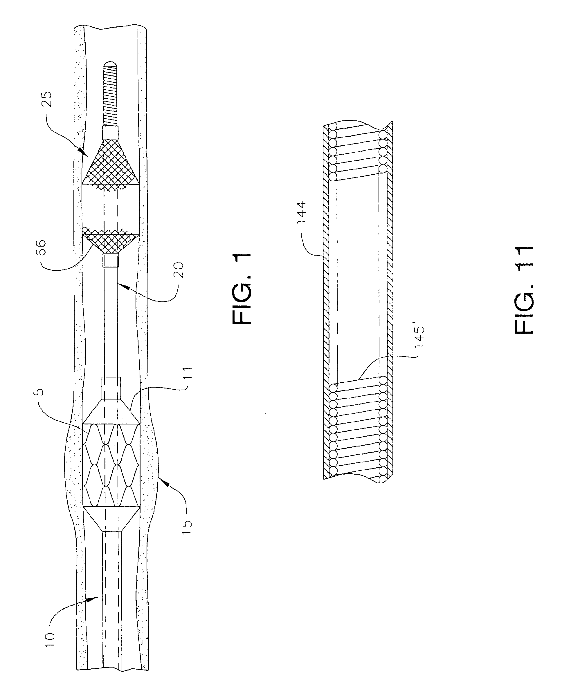
[0031]FIG. 6 depicts the invention in which filter guidewire 120 incorporates a number of elements similar to the elements that make up filter guidewire 20. Such similar elements will be identified with the same reference numerals throughout the description of the invention. Filter guidewire 120 includes core wire 142 and flexible tubular tip member 43 fixed around the distal end of core wire 142, similar to the arrangement of guidewire 20, supra. Hollow shaft 144 is movably disposed around core wire 142 and is comparable, throughout its length, to relatively stiff proximal portion 46 of filter guidewire 20. Filter 25 is positioned generally concentrically with core wire 142. Filter distal end 27 is fixedly coupled to tip member 43, and filter proximal end 29 is fixedly coupled near the distal end of shaft 144.

[0032]Optionally, a portion of core wire 142 within the proximal end of shaft 144 has one or more bends 160 formed therein. The amplitude, or maximal transverse dimension of b...

third embodiment

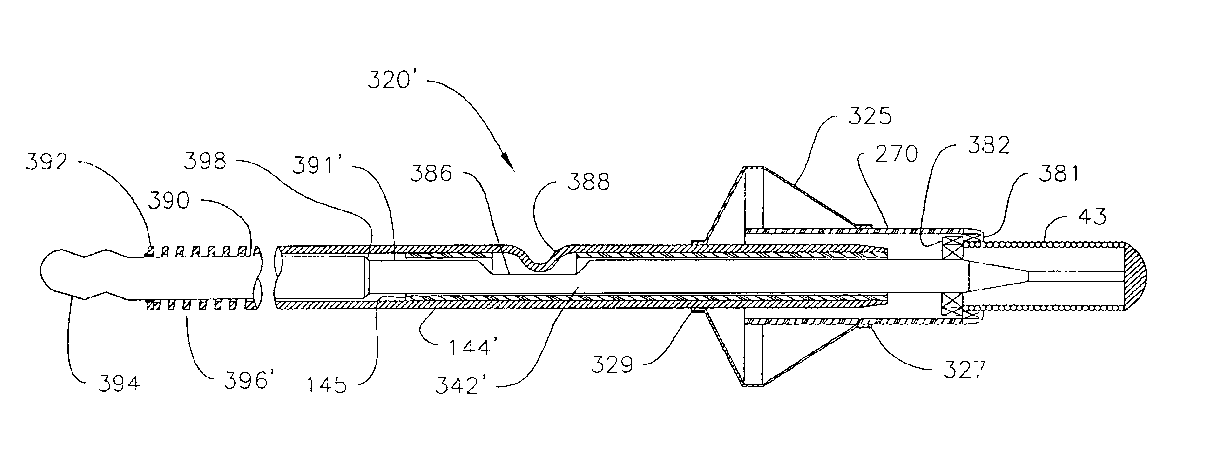
[0041]FIG. 12 depicts the invention in which filter guidewire 220 incorporates several elements that are similar to the components of filter guidewires 20 and 120. Core wire 242 is disposed within liner 145, which is disposed within hollow shaft 144. Core wire 242 is comprised of proximal section 256 and separate distal section 258, which extends distally from shaft 144. Sliding clearance(s) maybe formed between different elongate movable components, as described supra and as shown in FIGS. 7, 8 and 9. If liner 145 is fitted against core wire 242, as shown in FIG. 9, then liner 145 will comprise separate proximal and distal sections (not shown) corresponding to core wire proximal section 256 and core wire distal section 258. Flexible tubular tip member 43 is fixed around the distal end of core wire distal section 258. Transition sleeve 270 is slidably disposed about a distal portion of hollow shaft 144 and extends distally there from to a fixed coupling location on tip member 43. Fi...


PUM


Abstract

A guidewire apparatus for use during percutaneous catheter interventions, such as angioplasty or stent deployment. A protection element comprising a filter or an occluder is mounted near the distal end of a steerable guidewire, which guides a therapeutic catheter. The guidewire apparatus comprises a hollow shaft movably disposed about a core wire and, optionally, a slippery liner interfitted there between. The shaft and core wire control relative displacement of the ends of the protection element, causing transformation of the protection element between a deployed configuration and a collapsed configuration.

Description

CROSS-REFERENCE TO RELATED APPLICATION[0001]This patent application is a continuation-in-part of U.S. patent application Ser. No. 09 / 918,441 to Douk et al. filed Jul. 27, 2001, now U.S. Pat. No. 6,818,006, which is a continuation-in-part of U.S. patent application Ser. No. 09 / 824,832 to Douk et al. filed Apr. 3, 2001 entitled “Temporary Intraluminal Filter Guidewire and Methods of Use.”FIELD OF THE INVENTION[0002]The present invention relates generally to intraluminal devices for capturing particulate in the vessels of a patient. More particularly, the invention relates to a filter or an occluder for capturing emboli in a blood vessel during an interventional vascular procedure, then removing the captured emboli from the patient after completion of the procedure. Furthermore, the invention concerns a filter or an occluder mounted on a guidewire that can also be used to direct an interventional catheter to a treatment site within a patient.BACKGROUND OF THE INVENTION[0003]A variety o...

Claims


Application Information

Patent Timeline
Patent Type & Authority Patents(United States)
IPC IPC(8): A61B17/12A61F2/01A61B17/22A61B17/00A61B17/221A61M25/01
CPCA61B17/12022A61B17/12109A61B17/12172A61F2/013A61M25/09A61M25/09025A61B17/1204A61F2230/0071A61B2017/1205A61B2017/22038A61B2017/22045A61F2002/011A61F2002/015A61M2025/09008A61M2025/09183A61M2025/1015A61F2002/018A61F2230/0006A61F2230/0067A61F2/011
Inventor DOUK, NAREAKRAFIEE, NASSERSTRICKLER, PETER G.POOLE, MATT S.JENNINGS, ELLEN M.
Owner MEDTRONIC VASCULAR INC
Why Eureka
Try Eureka