Method and system for supplying high purity fluid

Inactive Publication Date: 2005-06-28
MATHESON TRI GAS
View PDF25 Cites 45 Cited by
  • Summary
  • Abstract
  • Description
  • Claims
  • Application Information

AI Technical Summary

Benefits of technology

[0010]One embodiment of the invention includes a fluid purifying apparatus comprising a vessel comprising a first interior compartment for containing a purifier material and a second interior compartment for containing a fluid having impurities, wherein the first interior compa

Problems solved by technology

These impurities can cause defects that reduce yields by increasing the number of rejects, which can be very expensive.
Although source fluid manufacturers typically provide analyses of source gas materials delivered to the semiconductor manufacturing facility, the purity of the fluids may change because of leakage into or outgassing of the containers, e.g., gas cylinders, in which gases are packaged.
Impurity contamination may also result from impr

Method used


Image

  • Method and system for supplying high purity fluid
  • Method and system for supplying high purity fluid
  • Method and system for supplying high purity fluid

Examples


Embodiment Construction

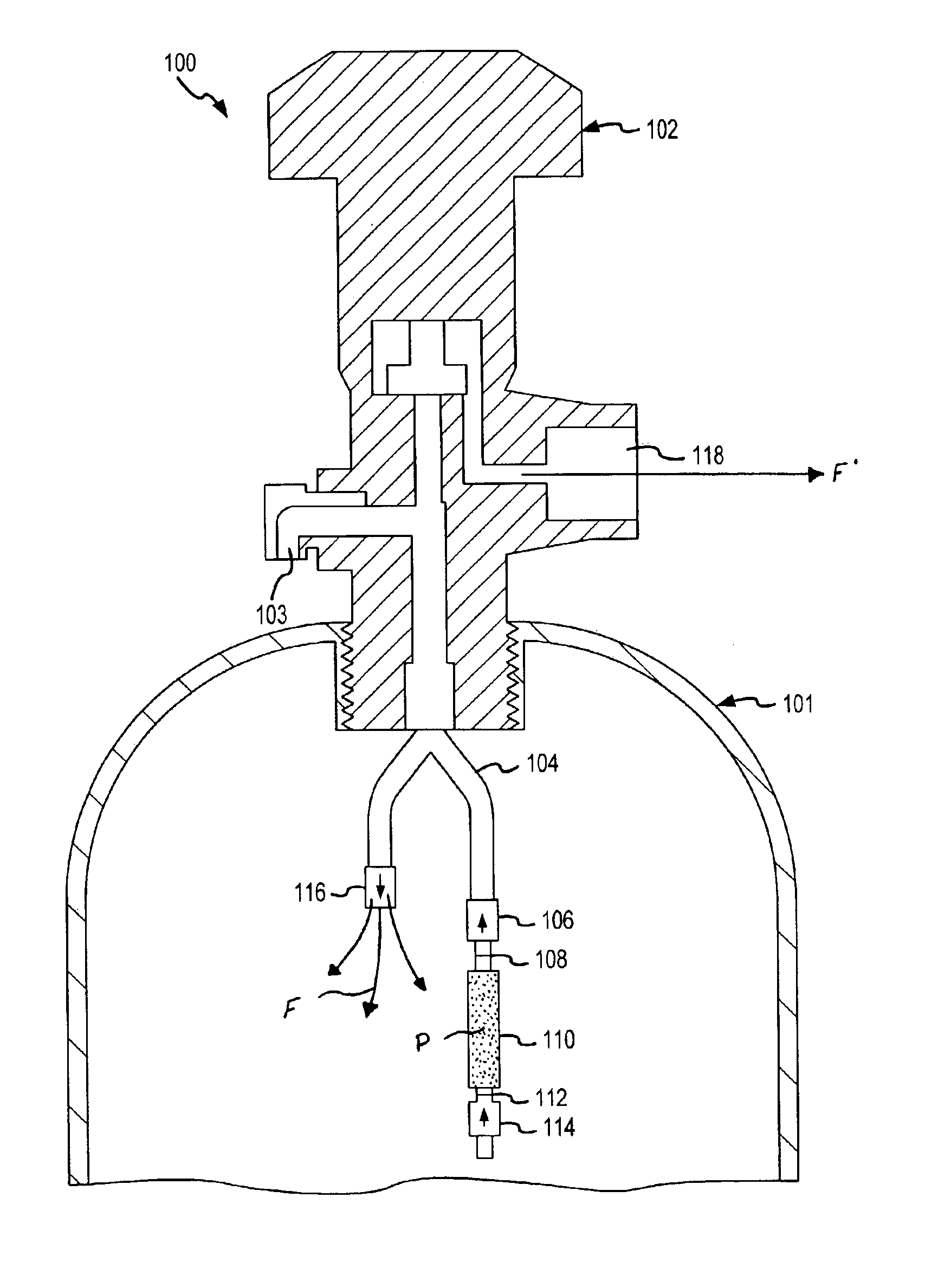
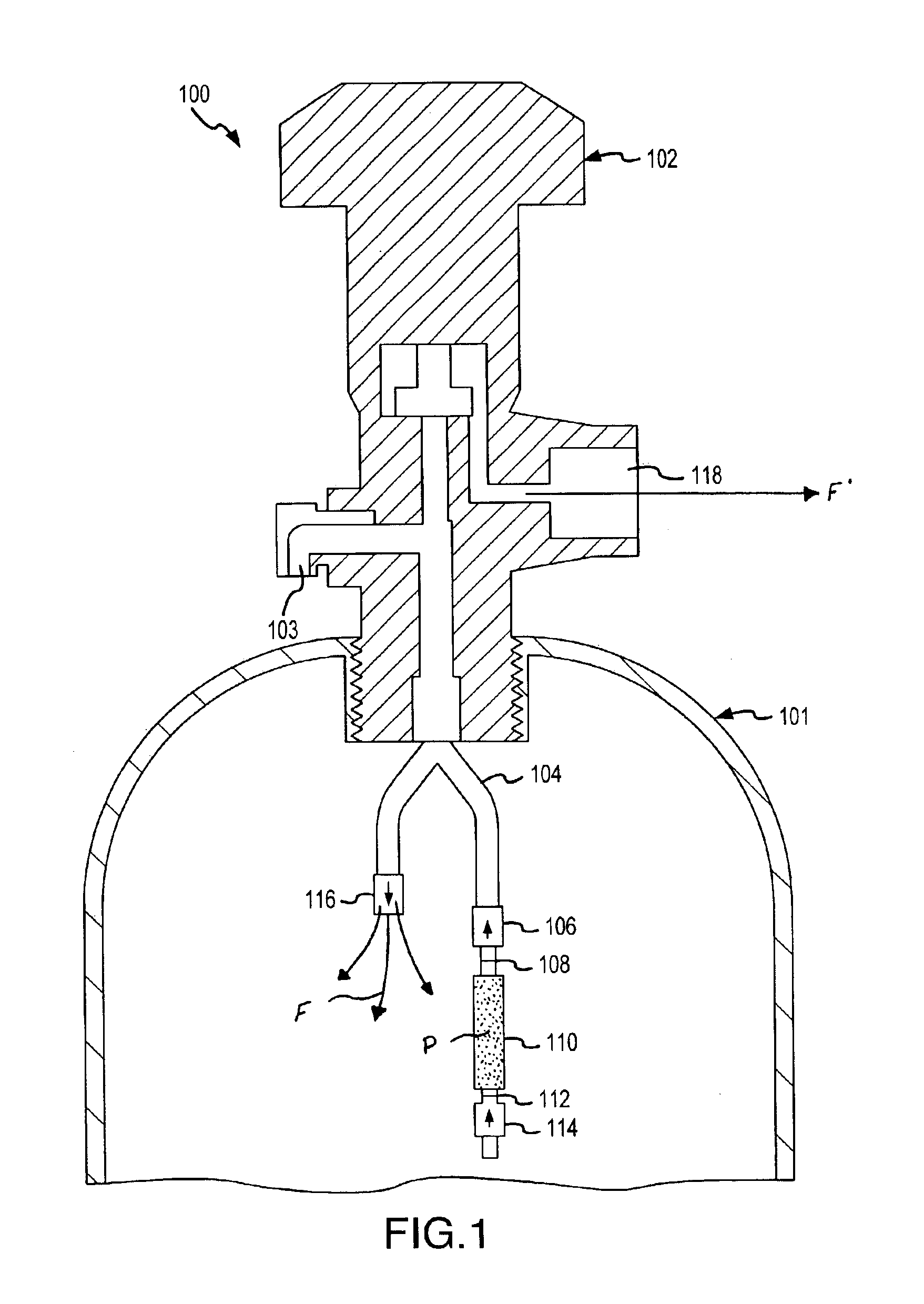
[0024]The fluid purifying apparatus 100 of the invention is illustrated by FIG. 1 and comprises a branched manifold 104 that is positioned inside a fluid storage vessel 101 and operatively engaged to a vessel valve 102 that receives fluids F and dispenses purified fluids F′ from the vessel 101. The individual elements of apparatus 100, such as the vessel 101, vessel valve 102, manifold 104, purifier unit 110, filter gaskets 108 and 112, and check valves 106, 114 and 116 will be discussed in further detail below. This branched manifold purifying apparatus 100 allows a user to introduce fluid F into storage vessel 101 through a branch of manifold 104 that terminates with check valve 116. The fluid F introduced to storage vessel 101 is then purified as it flows from storage vessel 101, through check valve 114, and into purifier unit 110 where impurities are removed by purifier material P located within purifier unit 110. The purified fluid F′ is dispensed from vessel valve 102 after ex...


PUM

PropertyMeasurementUnit
Pore sizeaaaaaaaaaa
Pore sizeaaaaaaaaaa
Specific surface areaaaaaaaaaaa

Abstract

A fluid purifying apparatus that includes a manifold that includes a first branch and a second branch, a first check valve coupled to the first branch of the manifold, and a purifier unit that includes a first end and a second end, wherein the first end is coupled to the second branch of the manifold. Also, a fluid purifying apparatus that includes a vessel that includes a first interior compartment for containing a purifier material and a second interior compartment for containment of a fluid containing impurities, wherein the first interior compartment is separated from the second interior compartment by a fluid permeable support, and a rupturable seal.

Description

BACKGROUND OF THE INVENTION[0001]1. Field of the Invention[0002]This invention relates to the field of fluid purification, and to the purification of inert, non-reactive and reactive fluids. Furthermore, the invention relates to methods and materials for selectively removing trace amounts of impurities from inert, non-reactive and reactive fluids.[0003]2. Description of the Prior Art[0004]The provision of high purity fluid streams is critically important in a wide variety of industrial and research applications. The rapid expansion of vapor-phase processing techniques, e.g., chemical vapor deposition, in the semiconductor industry has been associated with the deployment and use of manufacturing equipment that is totally reliant on the delivery of high purity process fluids at the point of use in the semiconductor manufacturing facility.[0005]Considering the impurities which ate present in fluid streams involved in semiconductor manufacturing, it is to be noted that the growth of hig...

Claims


Application Information

Patent Timeline
IPC IPC(8): B01D53/02B01J4/04C23C16/44F17C5/00F17C6/00F17C7/00F17C9/00F17C13/02
CPCB01D53/02B01J4/04C23C16/4402F17C5/00F17C6/00F17C7/00F17C9/00F17C13/026F17C2201/032F17C2201/0104F17C2205/0149F17C2205/0314F17C2205/0317F17C2205/0323F17C2205/0332F17C2205/0335F17C2205/0341F17C2205/0391F17C2221/05F17C2250/0631F17C2265/012Y02E60/321F17C2203/0617Y02E60/32B01D53/04
Inventor WATANABE, TADAHARUTORRES, JR., ROBERTVININSKI, JOSEPH
Owner MATHESON TRI GAS
Why Eureka
Try Eureka