Dosing device

a technology of dosing device and dosing chamber, which is applied in the direction of mixing, transportation and packaging, instruments, etc., can solve the problems of unnecessarily complex construction, and achieve the effect of reliable measurement and simple and elegant construction

Inactive Publication Date: 2005-06-28
E H KLIJN BEHEER
View PDF12 Cites 23 Cited by
  • Summary
  • Abstract
  • Description
  • Claims
  • Application Information

AI Technical Summary

Benefits of technology

[0007]According to the present invention a dosing device has a simple and elegant construction with which precise dosing is possible.
[0008]The weighing means preferably comprise a compensation for shifting the centre of gravity of the dosing device with the additive therein. Such a preferred embodiment is particularly favourable in respect of the above described narrowing in the passage for the basic flow, wherein the container can have a form corresponding with this narrowing. This, once again, to keep as short as possible the distance between the container for the additive and the passage for the basic flow, and hereby also the dosing mechanism. As the level of additive in the container falls, a shifting of the centre of gravity herein takes place which, in a configuration wherein the dosing mechanism is connected to the inlet via the weighing means, influences the weight weighed using the weighing means. This is particularly the case when the container is not wholly supported by the weighing means, but the weighing means actually form a connection between the inlet and the dosing mechanism. By providing the weighing means with such a compensation a reliable measurement of the weight of at least the container and the additive therein is obtained at all times, as well as a determination of the outflow at a set operation of the dosing mechanism, so that accurate dosing is possible, irrespective of any displacement or shifting of the centre of gravity of the container with the additive in a lateral direction.

Problems solved by technology

A drawback of the known art is that such constructions are usually unnecessarily complex, particularly when a narrowing occurs in the passage for the basic flow with raw material in the flow direction prior to a follow-on operation.

Method used


Image

  • Dosing device
  • Dosing device

Examples


Embodiment Construction

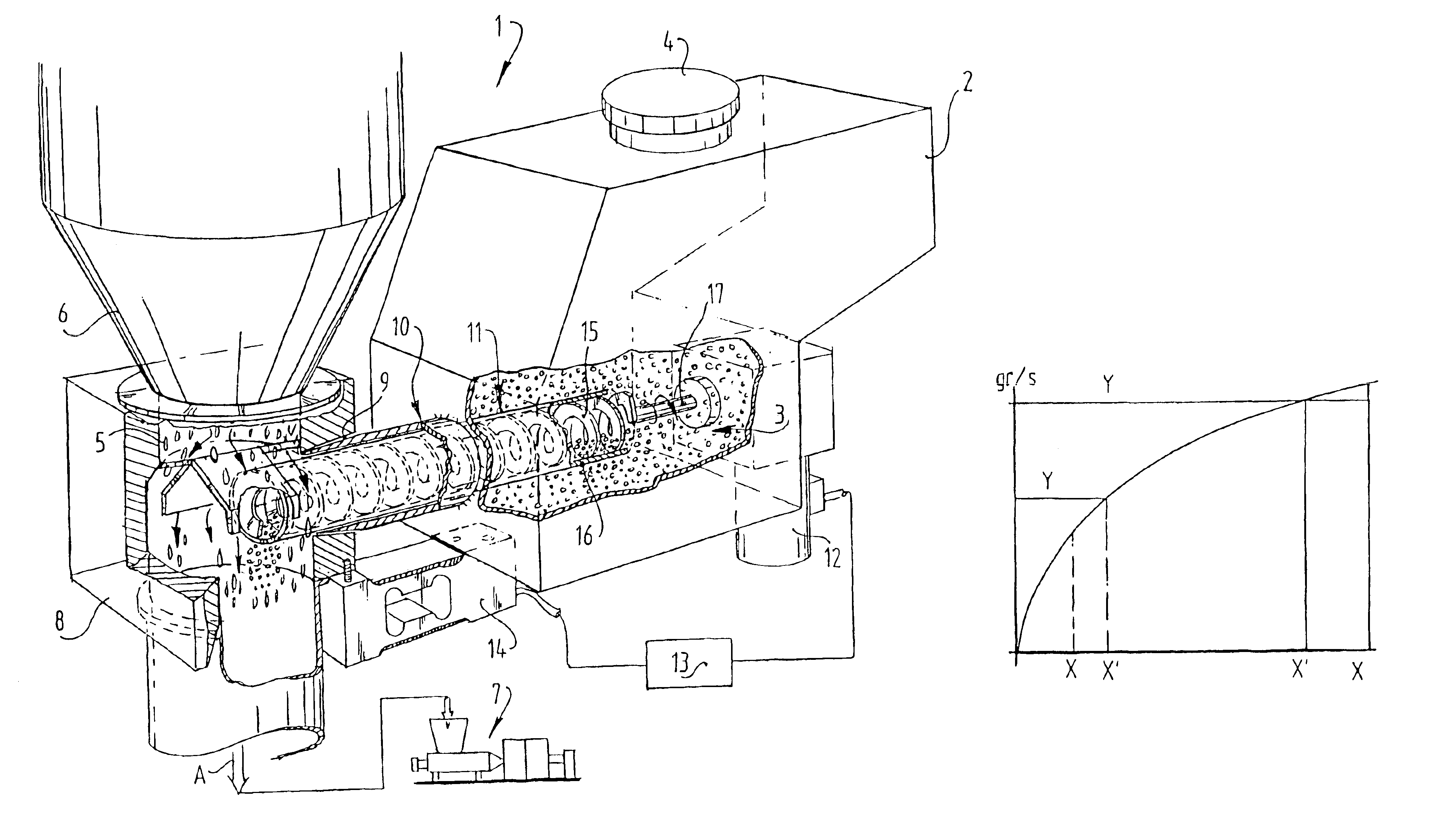
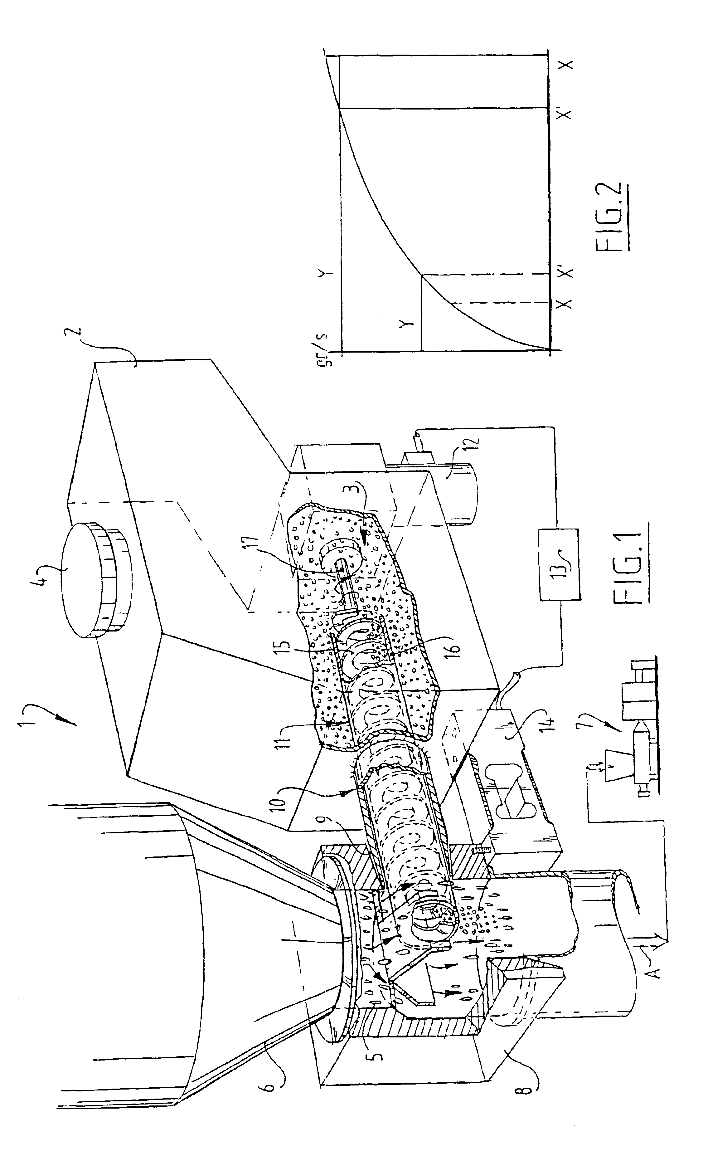
[0015]The dosing device 1 shown in FIG. 1 comprises a container 2 for additive 3, which can be introduced into container 2 using a filler cap 4. Additive 3 has to be added to a basic flow 5, which flows through a passage 6. A mixture of the basic flow 5 and the additive 3 added thereto is carried in the direction of arrow A to a further processing device 7, for instance an injection-moulding machine or an extruder.

[0016]Passage 6 debouches into a neck part 8 with an inlet 9 for infeed of additive 3. Placed into inlet 9 is a dosing mechanism 10 which comprises a dosing cylinder 11 for displacing additive 3 from container 2 to neck part 8.

[0017]Dosing cylinder 11 is connected to a motor 12, for instance a stepping motor, which is driven by a control 13, which is connected in turn to a load cell 14 of the single point type which forms weighing means, and which comprises a compensation for shifting the centre of gravity of the container with the additive 3 therein. A signal representati...


PUM

PropertyMeasurementUnit
weightaaaaaaaaaa
gravityaaaaaaaaaa
colouraaaaaaaaaa

Abstract

The invention relates to a dosing device for mixing additive into a basic flow, comprising: a passage for the basic flow; an inlet for the additive in the passage; a container for the additive connected to the inlet via a dosing mechanism and having a controllable drive for discharge of the additive into the inlet; weighing means for determining the weight of at least the container with the additive; and a control for the drive which is connected to the weighting means for setting a dosed discharge, wherein the dosing mechanism is arranged on the inlet via the weighing means.

Description

BACKGROUND OF THE INVENTION[0001]1. Field of the Invention[0002]The present invention relates to a dosing device for adding an additive to a basic flow. Such dosing devices are generally known, whereby for instance dye can be added to a raw material for an extrusion process so as to provide the finished product with colour.[0003]2. Description of the Related Art[0004]In such known dosing devices use is usually made of a rigid construction to arrange a container for the additive. Weighing means can then be placed between the rigid construction and the container for the additive.[0005]A drawback of the known art is that such constructions are usually unnecessarily complex, particularly when a narrowing occurs in the passage for the basic flow with raw material in the flow direction prior to a follow-on operation. It is desirable here to keep as short as possible the distance over which additive for dosing must be displaced by a dosing mechanism. This is desirable in order to obtain th...

Claims


Application Information

Patent Timeline
Patent Type & Authority Patents(United States)
IPC IPC(8): B01F15/04B01F15/02B01F5/00B01F5/26B29C45/18B29C47/10G01G19/34G01G19/00B01F3/00B01F3/18B01F25/90B29C48/03B29C48/29
CPCB01F5/26B01F15/0201B01F15/0234B01F15/0251G01G19/343B29C45/1816B29C47/1063B01F15/0445B01F3/18B29C47/0009B29K2105/0005B29C48/29B29C48/03B29B7/60B29B7/88B01F23/60B01F25/90B01F35/7173B01F35/71B01F35/71775B01F35/881B29B7/728
Inventor KLIJN, ERIK HANS
Owner E H KLIJN BEHEER
Why Eureka
Try Eureka