Glass-sealed light-emitting diode

Inactive Publication Date: 2005-06-28
STANLEY ELECTRIC CO LTD
View PDF3 Cites 68 Cited by
  • Summary
  • Abstract
  • Description
  • Claims
  • Application Information

AI Technical Summary

Benefits of technology

[0010]To solve the above problems, a first aspect of the present invention is directed to a glass-encapsulated light-emitting diode, which comprises an LED bare chip; a pair of electrodes each connected to the LED bare chip on an opposite side thereof; a pair of leads each connected to the electrodes and thereby arranged for the LED bare chip to be interposed between the leads along

Problems solved by technology

(1) When only the surface mounting components are implemented, a single-sided board with circuits formed only on one side functions sufficiently. In contrast, when the conventional light-emitting diode is mixed together, a double-sided through-hole board with circuits formed on both sides is required, which increases the cost of the printed circuit board.
(2) After the surface mounting components are implemented on the printed circuit board, it is required to solder the conventiona

Method used


Image

  • Glass-sealed light-emitting diode
  • Glass-sealed light-emitting diode
  • Glass-sealed light-emitting diode

Examples


Embodiment Construction

[0019]Preferred embodiments of the present invention will be described in detail below with reference to FIGS. 1-3 (giving the same reference numerals to the same parts). The below-described embodiments are simply suitable specified examples of the present invention. Therefore, though various technically preferred limitations are given, the scope of the invention is not limited to these embodiments so long as a special description for limiting the invention is not given in the following explanation.

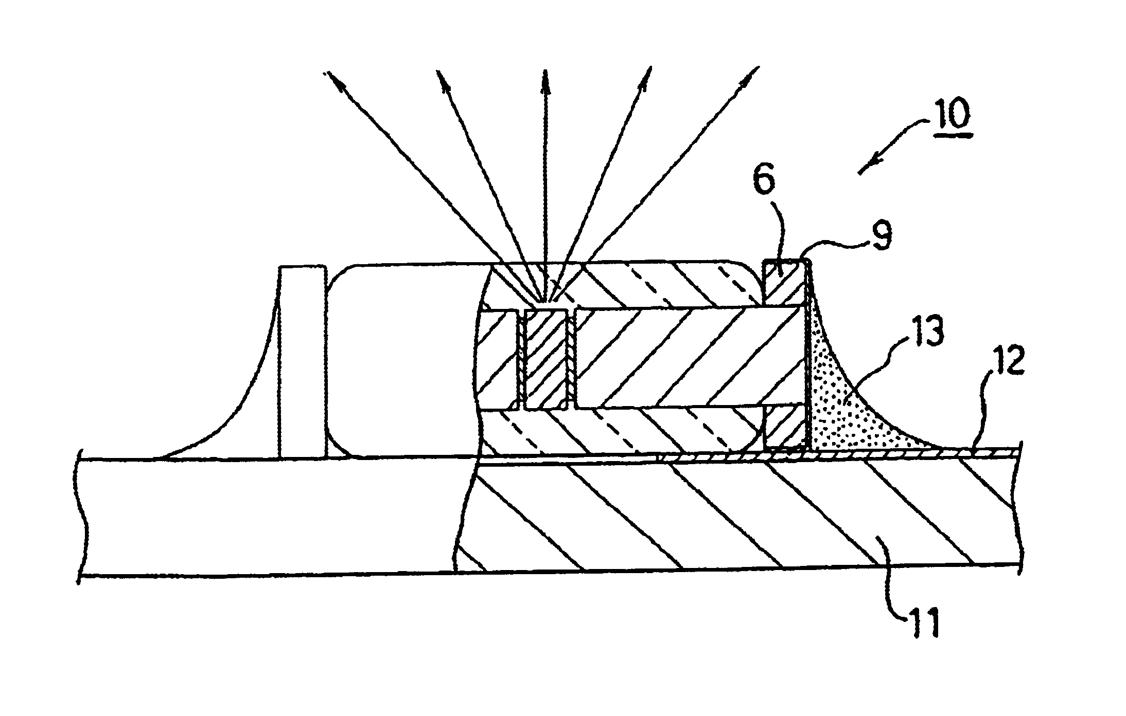
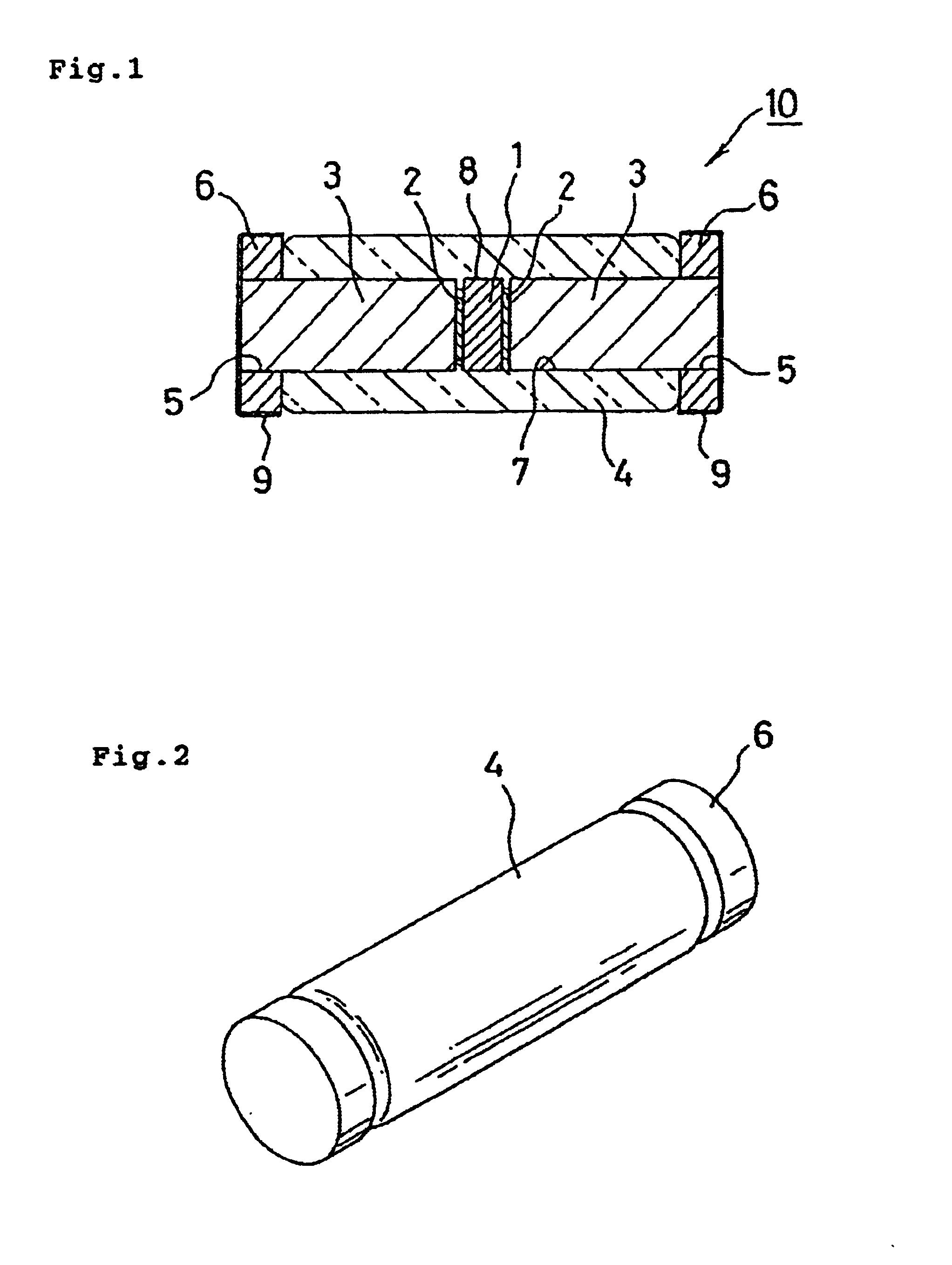
[0020]FIG. 1 is a transverse section showing an embodiment of the present invention and FIG. 2 is its perspective view. FIG. 3 is a partial cross-sectional view showing a glass-sealed light-emitting diode of the present invention implemented on a printed circuit board. As shown in FIG. 1, the glass-sealed light-emitting diode comprises an LED bare chip 1 having opposite surfaces, which are provided with electrodes 2 for supplying power from external. A pair of durnet wires 3 are each conn...


PUM


Abstract

A surface-mountable glass-sealed light-emitting diode is provided. It has high reliability and high external quantum efficiency, and can achieve a low-cost components-implemented board. An LED bare chip (1) has opposite surfaces, which are provided with electrodes (2) for supplying power from external. A pair of dumet wires (3) are separately connected to the respective electrodes (2) sandwiching the LED bare chip (1) therebetween. The LED bare chip (1), the electrodes (2) and parts of the dumet wires (3) are integrally glass-sealed (4). A pair of metallic disc plates (6) have holes (5) formed through the center. They are secured on both sides of the glass seal (4) and solder-plated, allowing the pair of dumet wires (3) projected from the glass seal to pass through the holes (5).

Description

BACKGROUND OF THE INVENTION[0001]1. Field of the Invention[0002]The present invention relates to a surface-mountable glass-sealed light-emitting diode including a glass-sealed LED bare chip.[0003]2. Description of the Related Art[0004]In a conventional glass-sealed light-emitting diode (LED), for example, a pair of leads 33 are connected to anode and cathode electrodes of an LED bare chip 31, respectively, as shown in FIG. 4. A glass seal 32 is employed to integrally cover connections between the LED bare chip 31 and electrodes and the leads 33 for hermetic sealing. In the light-emitting diode 30 thus configured, when power is supplied through the leads 33 to the LED bare chip 31, an active region thereof emits light, which is guided from the side of the LED bare chip 31 through the glass seal 32 and output to external. There is an incident light that is emitted from the active region in the LED bare chip 31 and arrives at an interface between the LED bare chip 31 and the glass seal...

Claims


Application Information

Patent Timeline
IPC IPC(8): H01L33/00H01L23/48H01L33/54H01L33/56
CPCH01L33/56H01L33/62H01L33/54H01L2924/0002H01L2924/00
Inventor FUJISAWA, SHIGEOSHOJI, IWAOWATANABE, TOSHIFUMI
Owner STANLEY ELECTRIC CO LTD
Why Eureka
Try Eureka