Method and apparatus providing imager pixel array with grating structure and imager device containing the same

a technology of imager and grating structure, applied in the field of semiconductor devices, can solve the problems of increasing processing time and the complexity of imagers, compromising the quantum efficiency of imagers, and affecting the quality of imagers,

Active Publication Date: 2007-12-27
APTINA IMAGING CORP
View PDF6 Cites 87 Cited by
  • Summary
  • Abstract
  • Description
  • Claims
  • Application Information

AI Technical Summary

Benefits of technology

[0011]FIGS. 2a and 2b show diffractive index charts of dispersive and less dispersive material pairs;

Problems solved by technology

When using the CFA technique to differentiate colors, the quantum efficiency of an imager can be compromised as color filters allow only a narrow spectral band of incident light (e.g., red, green, or blue light) to pass through while absorbing the rest of the photo energy.
Color filter arrays made by current CFA manufacturing processes can also be susceptible to a number of process issues, such as non-planarity and streaks, which can lead to fixed pattern noise and other defects.
Moreover, a captured image having individual color pixels must then be processed using a color demosaicing technique, which can increase processing time and the complexity of the imager.

Method used


Image

  • Method and apparatus providing imager pixel array with grating structure and imager device containing the same
  • Method and apparatus providing imager pixel array with grating structure and imager device containing the same
  • Method and apparatus providing imager pixel array with grating structure and imager device containing the same

Examples


Embodiment Construction

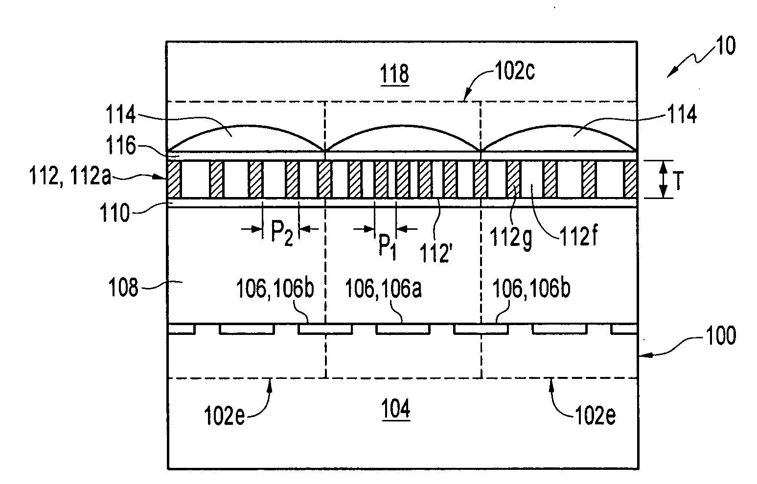
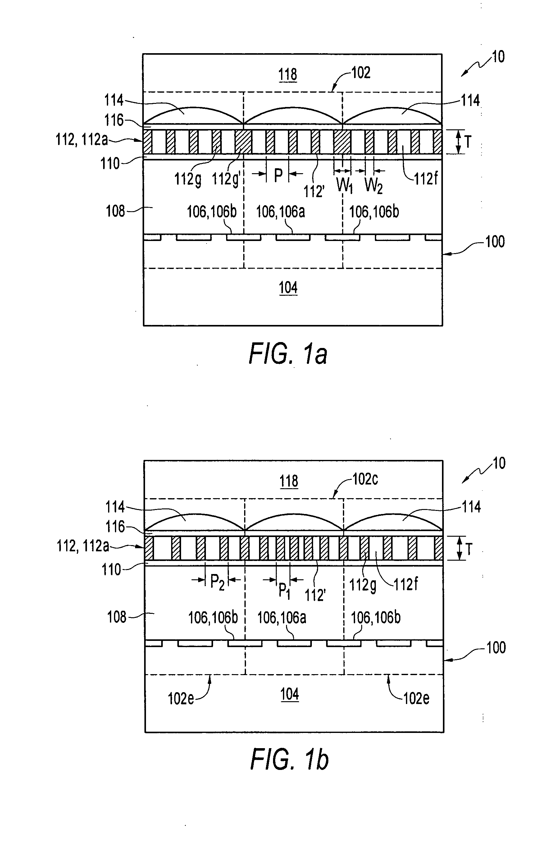
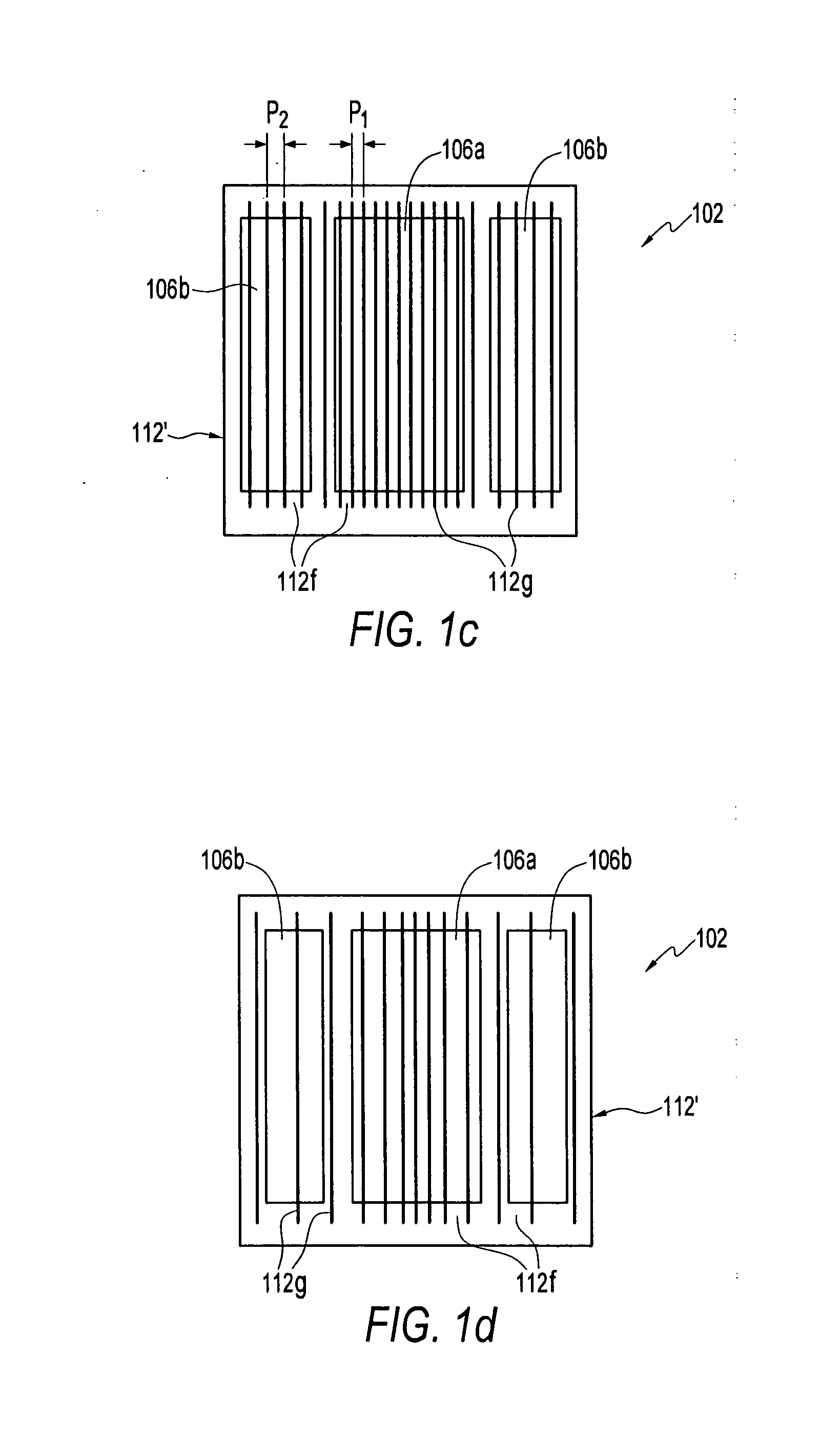
[0020]In the following detailed description, reference is made to the accompanying drawings, which form a part hereof and show by way of illustration specific embodiments and examples in which the invention may be practiced. These embodiments and examples are described in sufficient detail to enable those skilled in the art to practice the invention. It is to be understood that other embodiments may be utilized, and that structural, logical, and electrical changes may be made without departing from the spirit and scope of the invention.

[0021]The term “substrate” used in the following description may include any supporting structure including, but not limited to, a semiconductor substrate that has a surface on which devices can be fabricated. A semiconductor substrate should be understood to include silicon, silicon-on-insulator (SOI), silicon-on-sapphire (SOS), doped and undoped semiconductors, epitaxial layers of silicon supported by a base semiconductor foundation, and other semic...


PUM


Abstract

An imager pixel array capable of separating and detecting the spectral components of an incident light without the use of a color filter array. The imager pixel array employs a grating layer which allows one or more spectral components of incident light to be transmitted therethrough, but diffracts other spectral components of the incident light. Both the transmitted and diffracted spectral components can be sensed by photosensors in the imager pixel array and used in subsequent data processing, thereby improving the quantum efficiency of the imager device. The grating layer can be formed of first and second materials each having a refractive index which are substantially the same at a predetermined wavelength.

Description

FIELD OF THE INVENTION[0001]The invention relates generally to semiconductor devices, and in particular to imager pixel arrays and imager devices, and methods of forming the same.BACKGROUND OF THE INVENTION[0002]Solid state image sensors, also known as imagers, have commonly been used in various photo-imaging applications. An imager absorbs incident radiation of a particular wavelength (such as optical photons or x-rays) and generates an electrical signal corresponding to the absorbed radiation. There are a number of different types of semiconductor-based imagers, including charge coupled devices (CCDs), photodiode arrays, charge injection devices (CIDs), hybrid focal plan arrays, and complementary metal oxide semiconductor (CMOS) imagers. These imagers, when used with appropriate imaging circuits, capture, process and display images for various purposes. Current applications of solid state imagers include cameras, scanners, machine vision systems, vehicle navigation systems, video ...

Claims


Application Information

Patent Timeline
Patent Type & Authority Applications(United States)
IPC IPC(8): H01L21/00
CPCG02B5/1871G02B27/1013G02B27/1086H04N9/045H01L27/14627H01L27/14685H01L27/14625
Inventor YANG, ZHAOHUIBOETTIGER, ULRICH C.
Owner APTINA IMAGING CORP
Why Eureka
Try Eureka