X-Y stage system with onboard linear motor

a technology of linear motors and stage systems, applied in the direction of printing, instruments, manufacturing tools, etc., to achieve the effects of compact construction, less cost of production, and high accuracy

Active Publication Date: 2005-06-28
NIPPON THOMPSON
View PDF6 Cites 26 Cited by
  • Summary
  • Abstract
  • Description
  • Claims
  • Application Information

AI Technical Summary

Benefits of technology

[0010]The present invention, therefore, has as its primary object to overcome the subject as described just above and more particular to provide an X-Y stage system with onboard linear motor, which is made as small as possible in overall height, compact and simple in construction to provide easier and quicker assemble of parts and components, allowing the armature winding assembly to move without causing any interference in electrical cords during the movement of the X- and / or Y-stage, which might otherwise raise dust and dirt, thereby helping keep the sliding area against foreign matter, even with making sure of highly precise position control of the X- and Y-stages and far inexpensive production cost. It is a further object of the present invention to provide an X-Y stage system with onboard linear motor in which the armature windings and the field magnets are arranged in opposition to each other, any one for any of the turntable and the bed, the other for the residual one, thereby making it possible to extend largely an angular movement in circular direction for position control, rendering the position-control stage system itself reduced in overall height, compact and simple in construction, allowing the position-control stage system to work with high precision in clean environment and further produce the stage system with inexpensive cost.
[0020]According to the present invention, especially, the magnet yokes secured to the bed and the Y-stage respectively are made in a horse-shoe shape in cross section, inside which field magnets are installed in opposite relation to one another, while the armature winding assemblies are mounted on the opposite sides of the X-stage, one assembly to each side. To assemble the bed, X- and Y-stages into the X-Y stage system, the X-stage is first laid on the bed in a manner the armature winding assembly underneath the X-stage lying in a clearance open sidewise between the field magnets inside the horse-shoe shape magnet yoke on the bed, and then overlaid with the Y-stage in a manner another armature winding assembly above the X-stage lying in a clearance open sidewise between the field magnets inside the horse-shoe shape magnet yoke on the Y-stage. This arrangement described just above helps make the X-Y stage system itself simple in construction and easier to assemble the system. With the X-Y stage system constructed as stated earlier, both the X- and Y-stages are allowed to move precisely without getting influence from the attractive force due to the magnetic force because of the magnetic attraction created by the field magnets being offset in the magnet yoke. Moreover, the X-Y stage system can be produced inexpensive.
[0021]Assembling the X-Y stage system of the present invention can be done easily by only joining the components including the bed, X-stage, Y-stage and further the angular position-control means in sequence according to the prescribed process.
[0022]In the X-Y stage system according to the present invention, both the bed and the Y-stage are each incorporated thereon with the magnet yoke of U-shape in cross sections, on inside confronting surfaces of which field magnets are supported in opposition across the clearance, while the X-stage is provided on the opposite sides thereof with the armature winding assemblies, each of which lies in the associated clearance between the field magnets of any magnet yoke. The linear motors constructed as stated earlier help cancel out the magnetic attraction due to the field magnets in the magnet yokes, which attraction might otherwise negatively affect the movement of the X- and Y-stages. The linear motor constructed according to the present invention makes sure of highly precise sliding movement, helping construct the X-Y stage system itself far compact in construction and less in overall height, and also making it possible to assemble easily the X-Y stage system with inexpensive production cost.
[0024]Further assembling the angular position-control means with the X-Y stage system needs only to join the angular position-control means with the Y-stage. With the angular position-control means combined with the X-Y stage system of the present invention, the armature windings and the field magnets are arranged in opposition to each other around a circular plane. This circular arrangement of the armature windings and the field magnets makes certain of position control over a wider angular area in circular direction. Moreover, the armature winding wound in the flat shape and the field magnet made in the rectangular shape help render the X-Y stage system as thin or slim as possible in overall height, resulting in making the X-Y stage system itself compact in construction and also getting high accuracy under clean environment.
[0025]With the angular position-control means in which the armature windings and the field magnets are both made in the shape of flat rectangle to exploit their advantage of much less costly production, the armature windings and the field magnets, as opposed to the prior slider unit in which the armature windings and the field magnets are both arranged linearly, are juxtaposed respectively in circular direction, with a spacing between any adjacent two increasing in circular direction as a radial distance becomes larger. This circular arrangement in which the armature windings and the field magnets, both made in the shape of rectangle, simply lie on the disc surfaces in circular direction figures out to accomplish the precise position control or precise angular position control, with even simple in construction. In addition the angular position-control means can be produced much less costly.

Problems solved by technology

Thus, it remains a major challenge to provide a slider unit with onboard moving-magnet linear motor, which advances in conduction system for armature windings, selection of material for field magnet, selection of encoder high in resolving-power and fixture construction of sensor cords to make the slider unit nimble in operation, less in weight, compact and simple in construction, far more precise in position control as well as far more speedy in response of the X-Y table relatively to the bed, large in angle allowed for angular movement in circular direction upon position control, reduced in overall height as low as possible, and inexpensive in production cost.

Method used


Image

  • X-Y stage system with onboard linear motor
  • X-Y stage system with onboard linear motor
  • X-Y stage system with onboard linear motor

Examples


Embodiment Construction

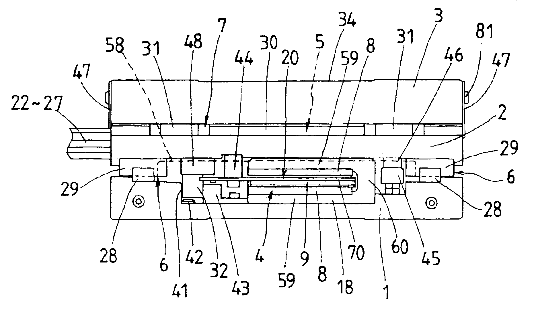
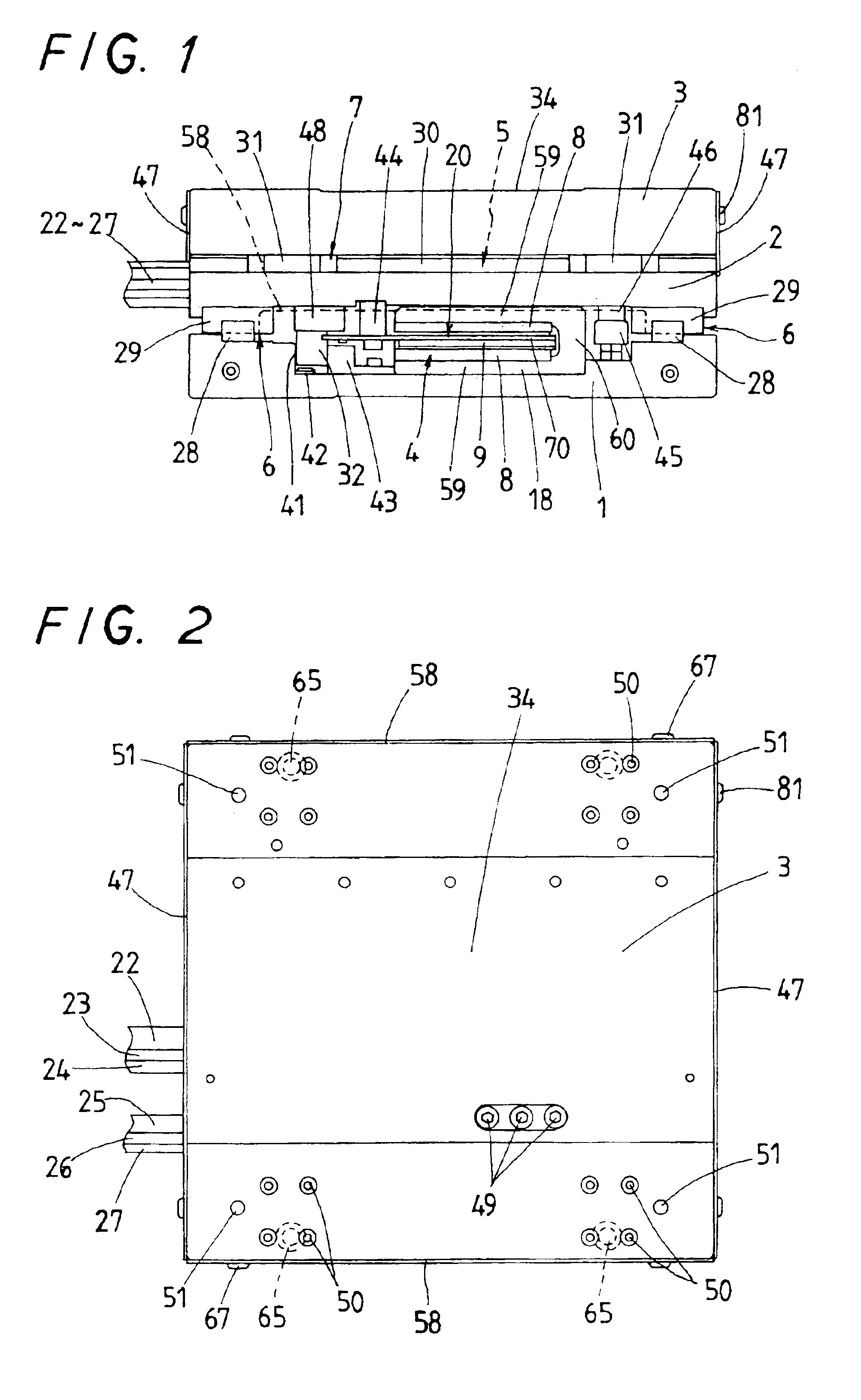
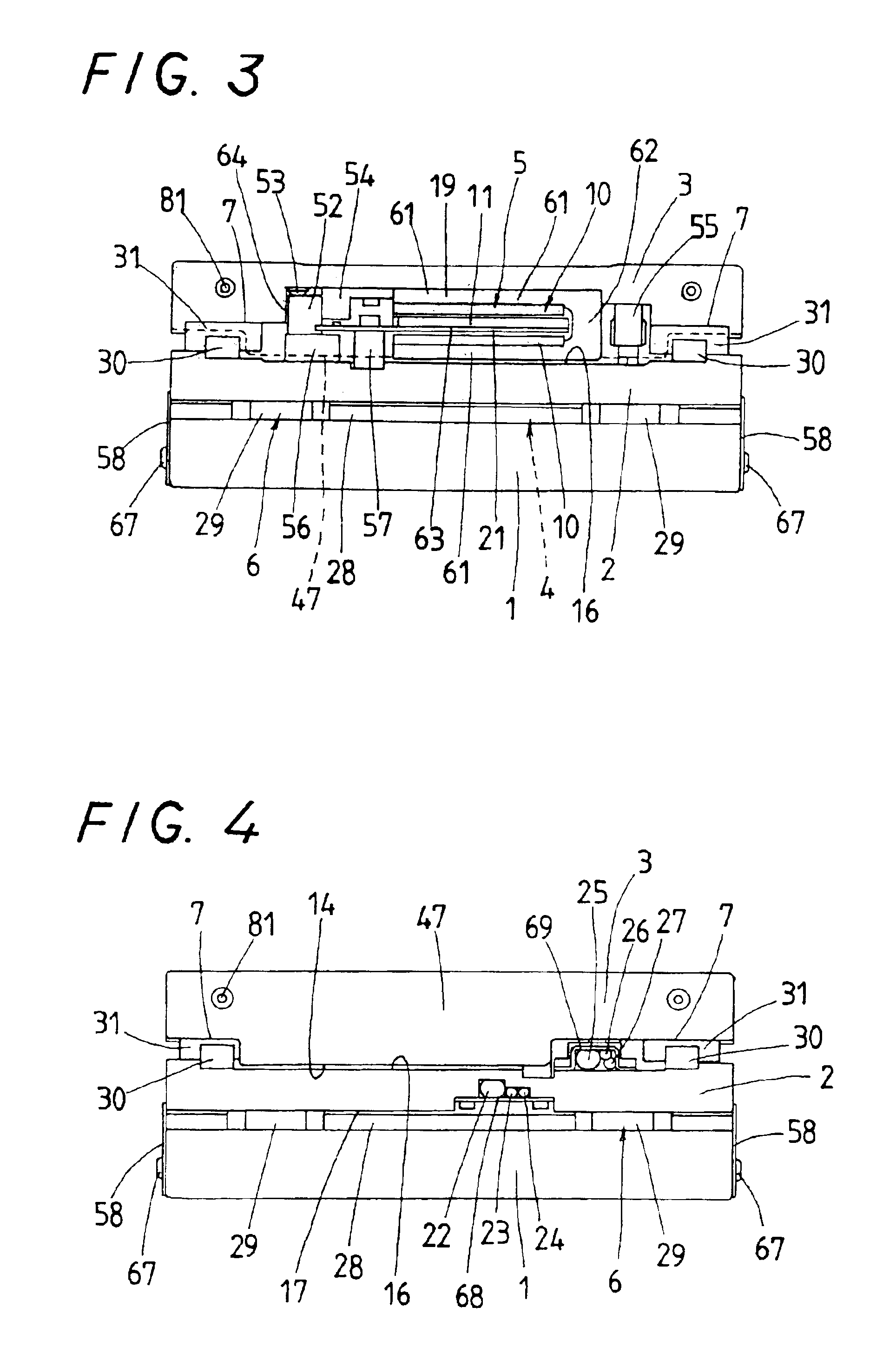
[0045]Preferred embodiments of an X-Y stage system according to the present invention will be explained hereinafter in detail with reference to the accompanying drawings. The X-Y stage system of the present invention is designed to serve well for machinery including semiconductor and liquid display manufacturing equipment, measuring instruments, assembling machines, tool machines, industrial robots, conveyors, and generally provided therein with onboard first and second linear motors. The first linear motor 4 is built in between an X-stage 2 and a stationary bed 1 and made up of first armature windings 9 lying below a lower surface 17 of the X-stage 2 and first field magnets 8 disposed on the stationary bed 1 in opposition to the first armature windings 9. The second linear motor 5 is built in between the X-stage 2 and a Y-stage 3 and made up of second armature windings 11 lying above an upper surface 16 of the X-stage 2 and second field magnets 10 disposed underneath the Y-stage 3 ...


PUM


Abstract

An X-Y stage system is disclosed which is easy to assemble and compact or slim in construction. Both the X- and Y-stages are allowed to move without getting influence from the magnetic force created by the field magnets. The X-Y stage system has an X-stage movable relatively to a bed through a linear motion guide unit in an X-direction, and a Y-stage movable relatively to the X-stage through another linear motion guide unit in a Y-direction. The linear motors to force the X- and Y-stages are composed of paired field magnets of secondary side held to the bed and the Y-stage, respectively, and armature windings of primary side supported on the opposite sides of the X-stage in a way lying in clearances between the opposing field magnets.

Description

BACKGROUND OF THE INVENTION[0001]1. Field of the Invention[0002]The present invention relates to an X-Y stage system with onboard linear motor, which has been extensively used in machinery including semiconductor and liquid display manufacturing equipment, measuring instruments, assembling machines, tool machines, industrial robots, conveyors and, more particularly, to an X-Y stage system with onboard linear motor in which an armature winding of primary side is installed on, for example, a turntable while a field magnet of secondary side lies on a stationary bed.[0003]2. Description of the Prior Art[0004]In recent years, current multi-axis stage systems and moving mechanisms such as X-Y plotters employed in the diverse technical fields using machinery as stated earlier have required more and more a position-control stage, which is made compact or slim in construction and light in weight, and moreover able to operate with high propulsion, high speed and high response to allow a movin...

Claims


Application Information

Patent Timeline
Patent Type & Authority Patents(United States)
IPC IPC(8): B23Q1/25B23Q1/62B23Q5/28B23Q5/22H02K41/03
CPCB23Q1/621H02K41/03B23Q5/28
Inventor TSUBOI, TAKAAKIIDA, EIJI
Owner NIPPON THOMPSON
Why Eureka
Try Eureka