Electromagnetic switching apparatus

a switching device and electromagnet technology, applied in the direction of electrical apparatus, electromagnetic relays, and electromagnet relay details, can solve the problems of increasing the number of parts of the device, affecting the operation of the device, so as to improve the magnetic efficiency of the driving section, improve the efficiency of the electromagnet, and reduce the number of devices

Inactive Publication Date: 2005-06-28
MATSUSHITA ELECTRIC WORKS LTD
View PDF8 Cites 100 Cited by
  • Summary
  • Abstract
  • Description
  • Claims
  • Application Information

AI Technical Summary

Benefits of technology

[0022]An object of this invention is to provide an electromagnetic switching device with improved energy-saving performance as compared with the conventional electromagnetic switching devices. Another object of this invention is to provide an electromagnetic switching device that enables to reduce the number of parts of the device while improving magnetic efficiency of an electromagnet of a driving section of the device. Yet another object of this invention is to provide an electromagnetic switching device that enables to suppress power consumption required by a coil constituting an electromagnet as compared with the conventional electromagnetic switching devices. Still another object of this invention is to provide an electromagnetic switching device having a mechanism with which a control circuit block is easily connectable with the device, with a simplified construction and at a low cost.

Problems solved by technology

Therefore, it is highly likely that switching performance of the device 1000 may be deteriorated owing to increase of the dimensions of the electromagnetic portion of the device 1000 or lowering of a spring load.
However, in the latter example where the cylindrical part has a three-piece structure, the number of parts constituting the device is increased, and the production cost is raised notwithstanding the improvement in magnetic efficiency of the electromagnetic portion.
However, in such a control, noise emitted from the coil is relatively large, which may adversely affect electronic parts in the vicinity of the coil and the electromagnetic switching device, etc.

Method used


Image

  • Electromagnetic switching apparatus
  • Electromagnetic switching apparatus
  • Electromagnetic switching apparatus

Examples


first embodiment

(First Embodiment)

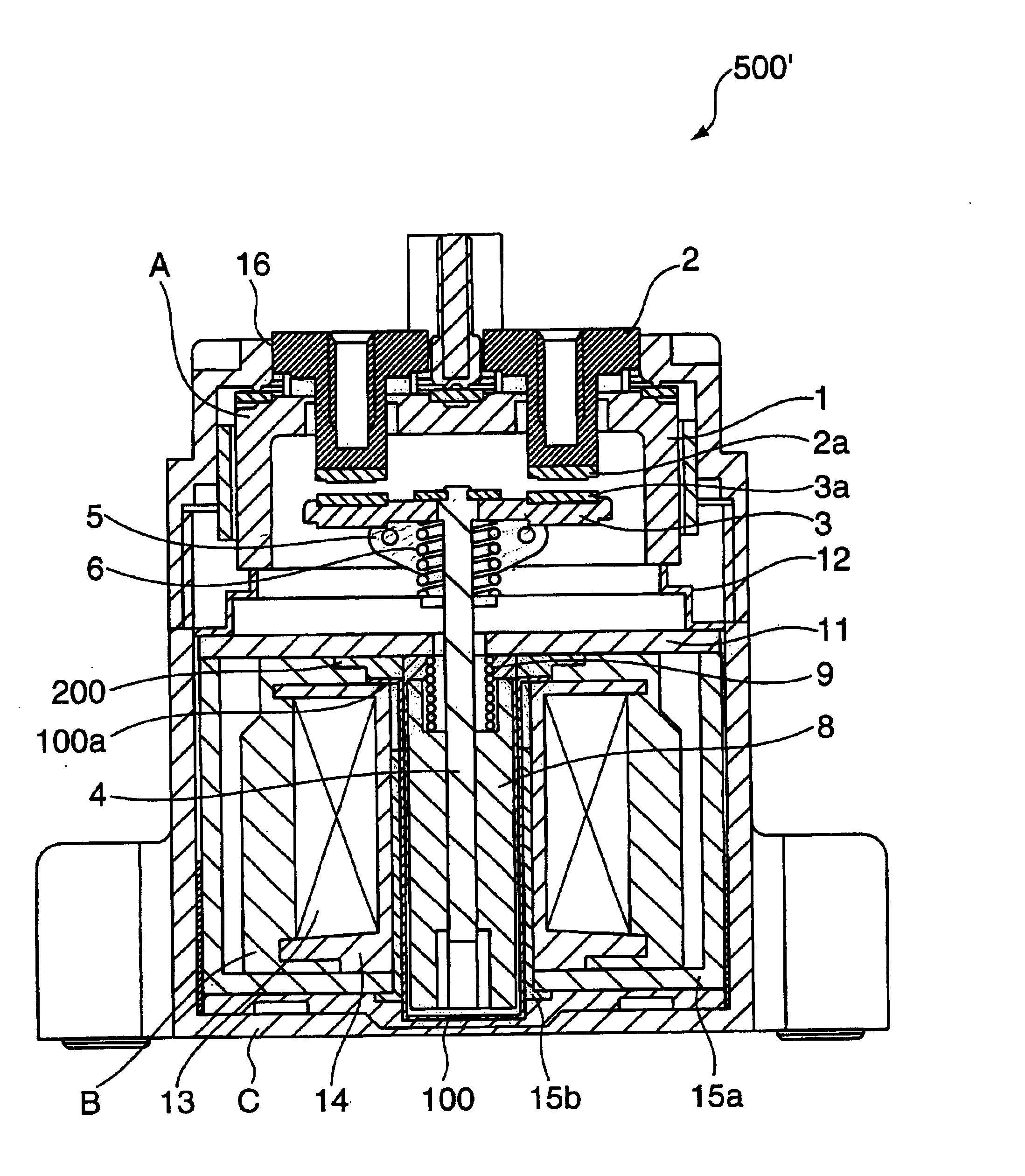
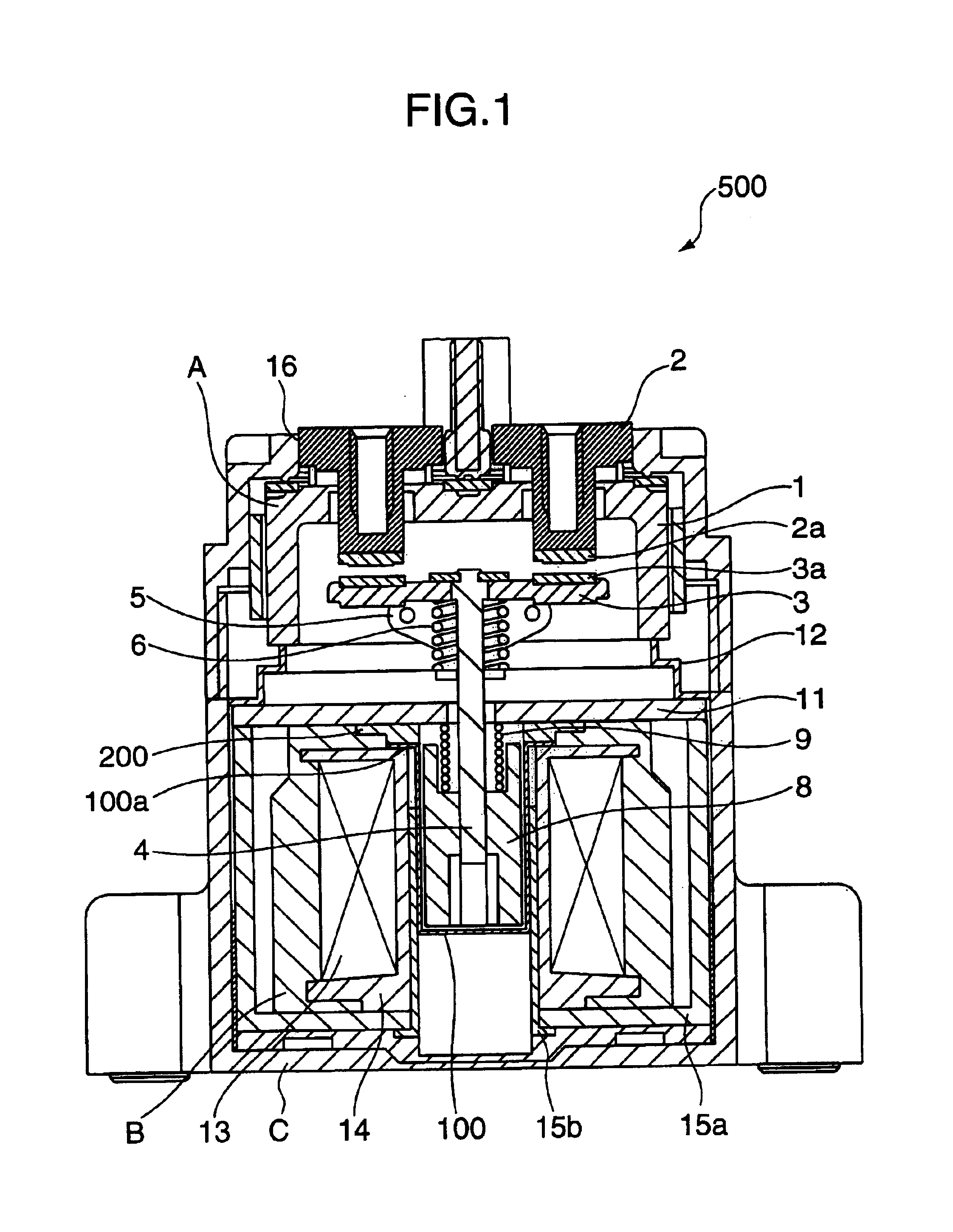
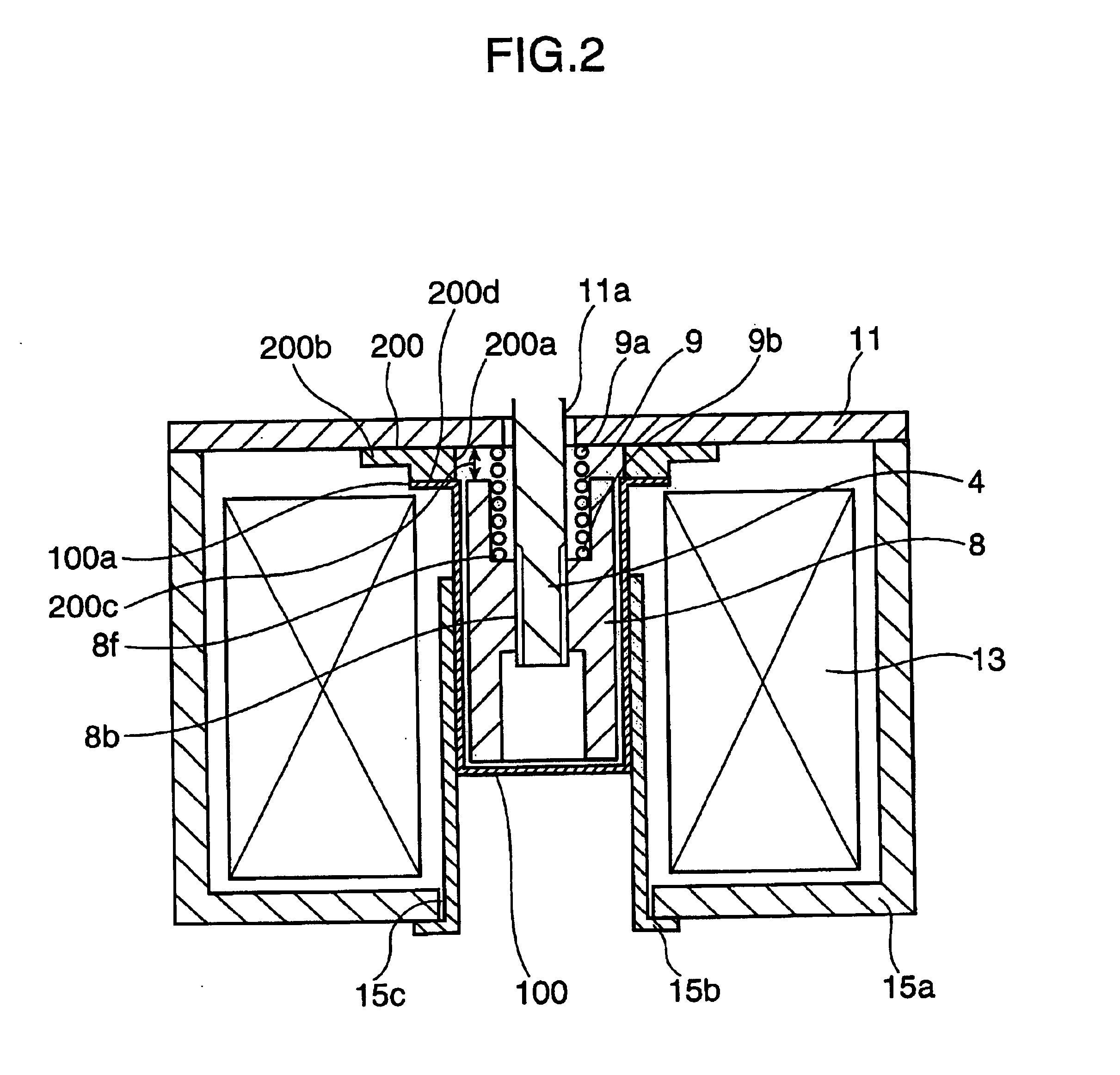
[0050]FIG. 1 is a side view in cross section showing an electromagnetic switching device as a first embodiment of this invention. Since the basic construction of the first electromagnetic switching device is identical to that of the conventional device, merely the characterizing part of the first electromagnetic switching device will be described herein. Specifically, the first electromagnetic switching device 500 including a sealed contact device is different from the conventional electromagnetic switching device 1000 including a conventional sealed contact device in that: the fixed iron core 7 in FIG. 21 is eliminated; a cylindrical member 100 made of a magnetic material with a closed bottom is provided in place of the cylindrical member 10 made of a non-magnetic material as shown in FIG. 21; a metal plate 200 made of a non-magnetic material is provided between the cylindrical member 100 and a first joint member 11; and the respective parts are air-tightly jointe...

second embodiment

(Second Embodiment)

[0056]FIG. 4 is a side view in cross section showing essential parts of an electromagnetic switching device as a second embodiment of this invention. Since the basic construction of the second electromagnetic switching device is identical to that of the conventional device, merely the characterizing part of the second electromagnetic switching device will be described herein. Specifically, the second electromagnetic switching device including a sealed contact device is different from the conventional electromagnetic switching device 1000 including a conventional sealed contact device in that: the fixed iron core 7 in FIG. 21 is eliminated; a cylindrical member 100 made of a magnetic material with a closed bottom is provided in place of the cylindrical member 10 made of a non-magnetic material shown in FIG. 21; a metal plate 300 made of a non-magnetic material is provided between the cylindrical member 100 and a first joint member 11; and the respective parts are a...

third embodiment

(Third Embodiment)

[0061]FIGS. 5 through 8 are an illustration showing an electromagnetic switching device as the third embodiment of this invention. FIGS. 5 and 6 are a front view in section and a side view in section showing the third device. FIG. 7 is a top plan view in section showing a coil. FIG. 8 is a circuit diagram for explaining a circuit for use in the third device.

[0062]The third electromagnetic switching device 501 including a sealed contact device comprises a sealing vessel 1 made of an insulating material, fixed terminals 2, 2 having fixed contacts 2a, 2a to be air-tightly jointed to the sealing vessel 1, a movable contact piece 3 which is movable toward and away from the fixed contacts 2a, 2a, a movable iron core 8 which is movable in one direction, a cylindrical member 10 with a dosed bottom for housing a movable iron core 8 therein, a first joint member 11 to be air-tightly jointed to the cylindrical member 10, a movable shaft 4 coupled to the movable iron core 8, a...


PUM


Abstract

In an electromagnetic switching device including a cylindrical part made of a magnetic material with a closed bottom for housing a movable iron core having a movable contact and so constructed as to render the movable contact movable toward and away from a fixed contact, a joint member made of a metallic material with an insertion hole formed substantially in the center thereof for movably receiving a movable shaft fixedly attached to the movable iron core, and a metal plate made of a non-magnetic material with a hole formed substantially in the center thereof with the inner diameter substantially the same as the inner diameter of the cylindrical part, the cylindrical part and the joint member are air-tightly jointed to each other with the metal plate provided therebetween, and the movable iron core is housed in the cylindrical part with a clearance defined between the movable iron core and the joint member corresponding to a required stroke within which the movable contact contacts the fixed contact. This arrangement provides improvement in magnetic efficiency of electromagnet of the device. Accordingly, improved energy saving performance is accomplished as compared with a case of a conventional electromagnetic switching device.

Description

TECHNICAL FIELD[0001]This invention relates to an electromagnetic switching device including a sealed contact device, which is suitable as a relay for power-driven load.BACKGROUND ART[0002]There has been proposed, as shown in FIG. 21, an electromagnetic switching device 1000 including a sealed contact device, which is disclosed in Japanese Patent No. 3107288 (corresponding to Japanese Unexamined Patent Publication No. 9-259728). The device 1000 is constructed such that a relay contact portion is housed in a hermetically sealed or air-tight space. With this arrangement, since there is no likelihood that arc generated in opening the contacts may leaked out of the device, this arrangement obviates a space for escaping arc which has been necessary in an air switching device, and makes it possible to mount parts in close contact with the device to raise the packaging density. The device 1000 is constructed as follows.[0003]Referring to FIG. 21, the electromagnetic switching device 1000 c...

Claims


Application Information

Patent Timeline
Patent Type & Authority Patents(United States)
IPC IPC(8): H01H50/36H01H51/00H01H50/00H01H50/16H01H50/20H01H47/06H01H47/08H01H50/44H01H50/22H01H47/00H01H51/28H01H50/54H01H50/02
CPCH01H47/06H01H47/08H01H50/20H01H50/36H01H50/443H01H51/28H01H50/22H01H50/023H01H2050/025H01H50/546H01H50/54
Inventor UOTOME, RIICHIENOMOTO, HIDEKIYAMAMOTO, RITSUKISHI, HIDEKI
Owner MATSUSHITA ELECTRIC WORKS LTD
Why Eureka
Try Eureka