
Optical micro-electromechanical systems (MEMS) devices and methods of making same

Inactive Publication Date: 2005-06-28
WSOU INVESTMENTS LLC +1
View PDF11 Cites 8 Cited by
  • Summary
  • Abstract
  • Description
  • Claims
  • Application Information

AI Technical Summary

Benefits of technology

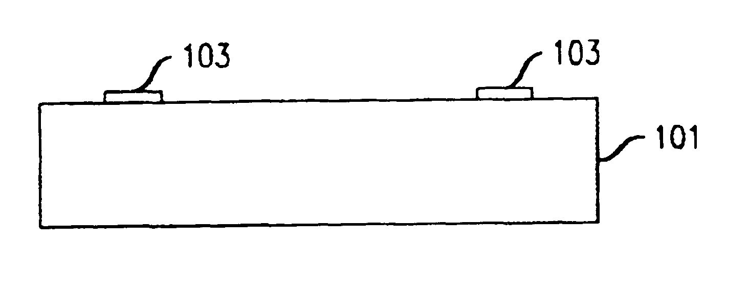
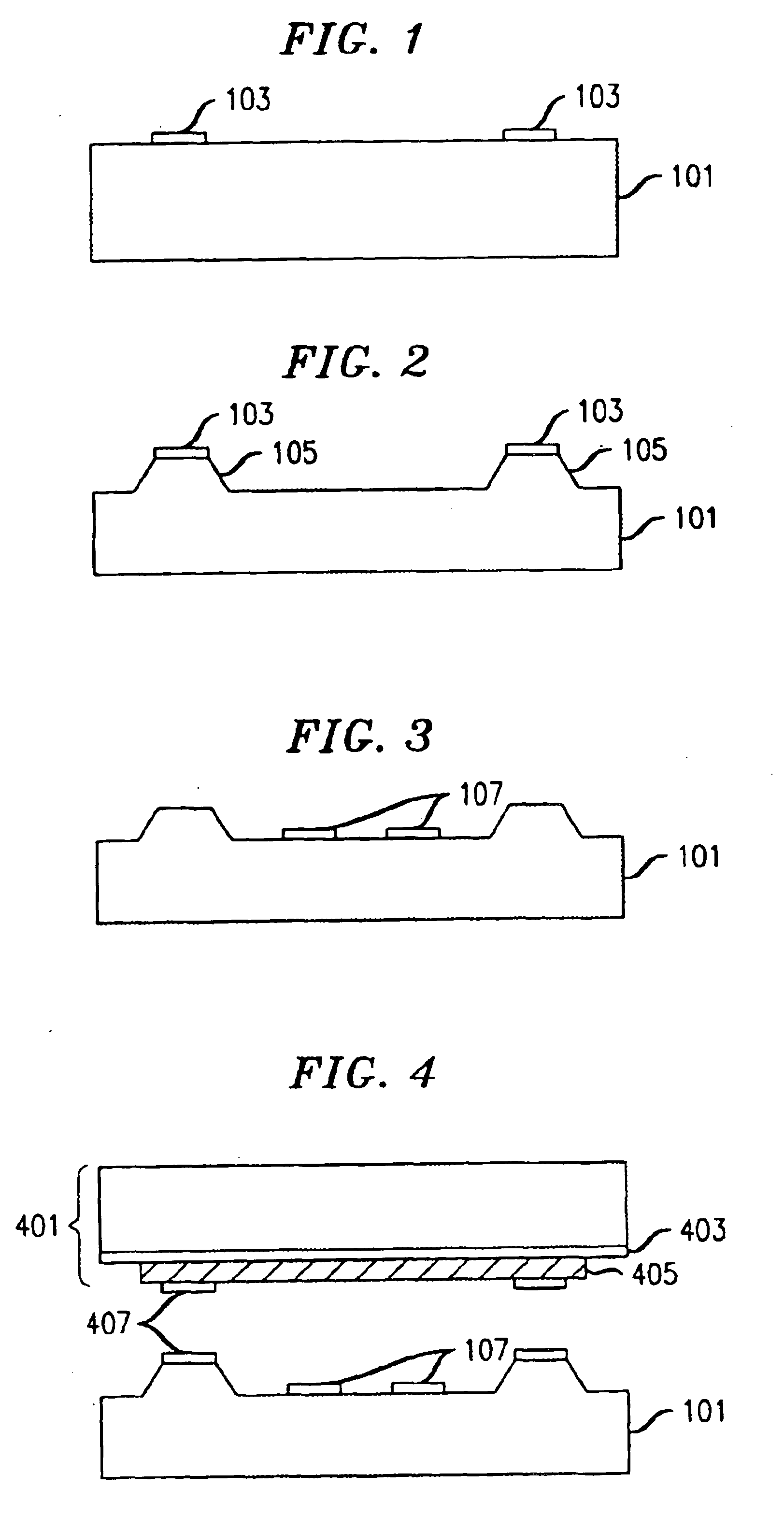
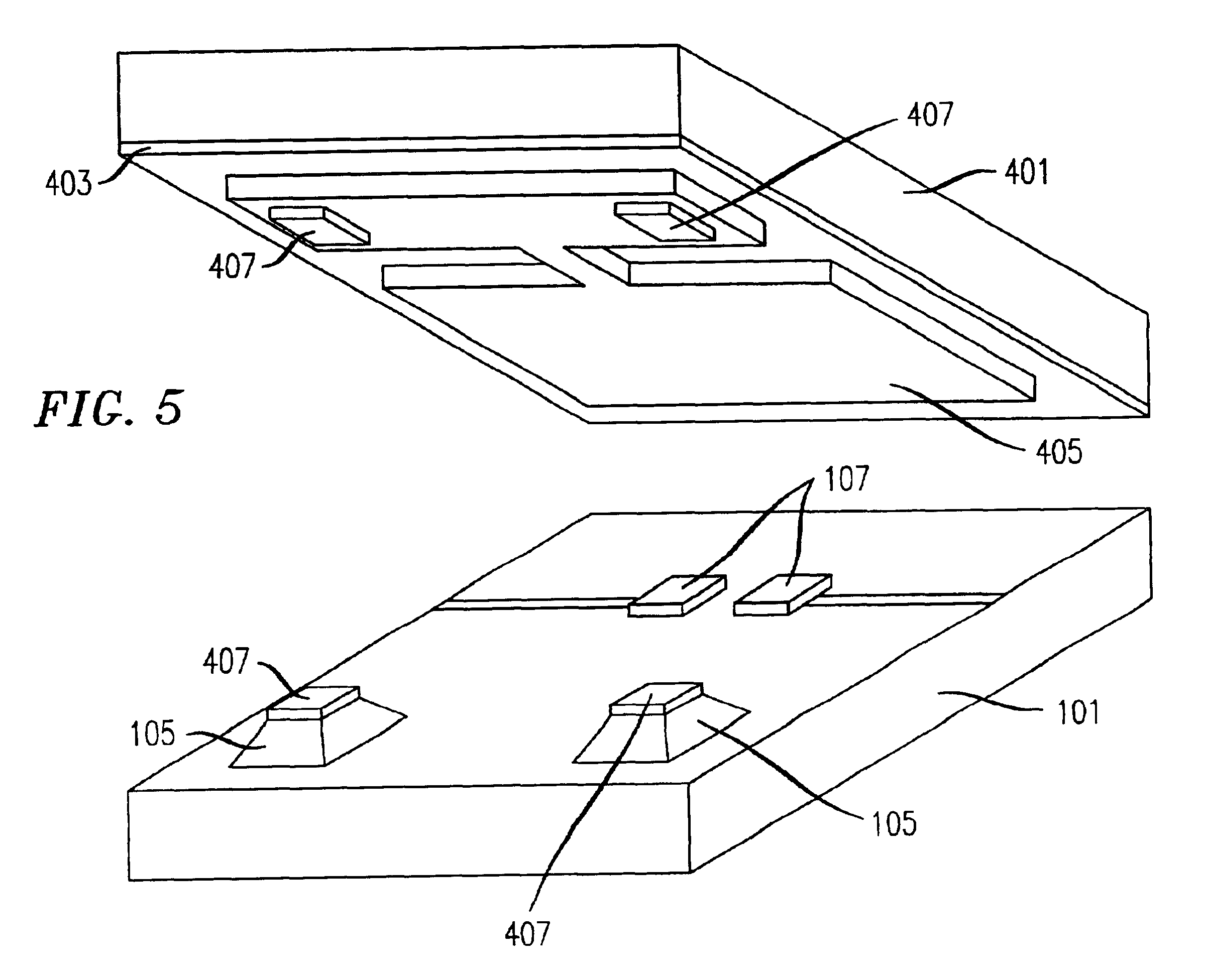
[0008]I have recognized that MEMS devices with an arbitrary gap between the two chips in a flip-chip arrangement can easily be achieved, in accordance with the principles of the invention, by etching into a first substrate to form mesas which act as the spacers and between which, or even on which, any requ

Problems solved by technology

Disadvantageously, such spacers are a) not flat at the top, b) are relatively soft, e.g., compared to silicon, c) must be hard baked at high temperatures, and d) the height of the resulting spacers is not uniform from device to device even when the same processing is employed.
However, such micro mirrors are relatively fragile, and the height of the spacers is dictated by the thickness of the wafer on which the micro mirrors were formed, which is typically greater than 200 μm.
This

Method used


Image

  • Optical micro-electromechanical systems (MEMS) devices and methods of making same
  • Optical micro-electromechanical systems (MEMS) devices and methods of making same
  • Optical micro-electromechanical systems (MEMS) devices and methods of making same

Examples


Example

[0029]The following merely illustrates the principles of the invention. It will thus be appreciated that those skilled in the art will be able to devise various arrangements which, although not explicitly described or shown herein, embody the principles of the invention and are included within its spirit and scope. Furthermore, all examples and conditional language recited herein are principally intended expressly to be only for pedagogical purposes to aid the reader in understanding the principles of the invention and the concepts contributed by the inventor(s) to furthering the art, and are to be construed as being without limitation to such specifically recited examples and conditions. Moreover, all statements herein reciting principles, aspects, and embodiments of the invention, as well as specific examples thereof, are intended to encompass both structural and functional equivalents thereof. Additionally, it is intended that such equivalents include both currently known equival...


PUM

PropertyMeasurementUnit
Structureaaaaaaaaaa
Shapeaaaaaaaaaa
Areaaaaaaaaaaa

Abstract

An arbitrary gap between the two chips of a MEMS device arranged in a flip-chip arrangement is achieved by etching into a first substrate to form mesas which act as spacers between which, or even on which, any required circuit elements are formed. Points of a layer at a first surface of the second substrate within which MEMS structures are made are bonded to the mesas of the first substrate. The second substrate is then removed, leaving the structures bonded to the mesas. The mesas may be formed by placing a hard mask, such as silicon oxide, which defines the desired pattern of mesas on the first substrate, and then etching the unmasked portion of the substrate using a mixture of potassium hydroxide (KOH) with isopropanol (IPA) or, tetramethyl ammonium hydroxide (TMAH) mixed with a surfactant, e.g., nonylphenol ethoxy ether or other equivalent compounds.

Description

TECHNICAL FIELD[0001]This invention relates to the art of micro-electromechanical systems (MEMS) devices and methods of their making, and more particularly, to arrays of tiltable micro mirrors, e.g., small mirrors, which can reflect light.BACKGROUND OF THE INVENTION[0002]One solution for all-optical switching employs two MEMS devices each containing an array of tiltable micro mirrors, e.g., small mirrors, which can reflect light, which herein refers to any radiation in the wavelength of interest, whether or not in the visible spectrum. An optical path is established for light supplied from an input source, e.g., an optical fiber, to an output, e.g., an output fiber, by steering the light using a first micro mirror on the first optical MEMS device, the first micro mirror being associated with the input fiber, onto a second micro mirror on the second optical MEMS device which is associated with the output fiber. The second micro mirror then steers the light into the output fiber. Each...

Claims


Application Information

Patent Timeline
IPC IPC(8): B81C1/00G02B26/08
CPCB81C1/00357G02B26/0841B81C2201/019
Inventor BOLLE, CRISTIAN APACZKOWSKI, MARK ANTHONY
Owner WSOU INVESTMENTS LLC
Learn More