Power injector apparatus

a technology of injectors and injectors, applied in the direction of electric variable regulation, process and machine control, instruments, etc., can solve the problems of increasing costs, unable to provide power outlets at places, and conventional frameworks have some problems

Active Publication Date: 2005-06-28
ACCTON TECHNOLOGY CORPORATION
View PDF4 Cites 37 Cited by
  • Summary
  • Abstract
  • Description
  • Claims
  • Application Information

AI Technical Summary

Benefits of technology

[0006]The other object of the present invention is to provide a power injector apparatus that can avoid the Internet apparatus failing to work normally when the Internet apparatus requires power that exceed the power that the Hub or the Switch supplies.
[0007]Accordingly, the present invention provides a power injector apparatus that can supply two power sources, one from the Internet and the other from AC power. The Internet device can select the AC power to supply power when the Internet device requires power that exceeds the power that the Hub or the Switch supplies, and thus avoid the malfunction of the Internet device due to power shortage. Moreover, the Internet device can also select the Ethernet power source when the supplied power is sufficient.

Problems solved by technology

In general, such higher places do not provide a power outlet.
An additional power arrangement, therefore, is required for providing power to the base station, which increases costs.
However, the conventional framework has some problems.
For example, if the Internet apparatus are not compatible with the POE specification or requires power that exceeds the central apparatus can supply, the conventional central apparatus fail to work.

Method used


Image

  • Power injector apparatus
  • Power injector apparatus
  • Power injector apparatus

Examples


first embodiment

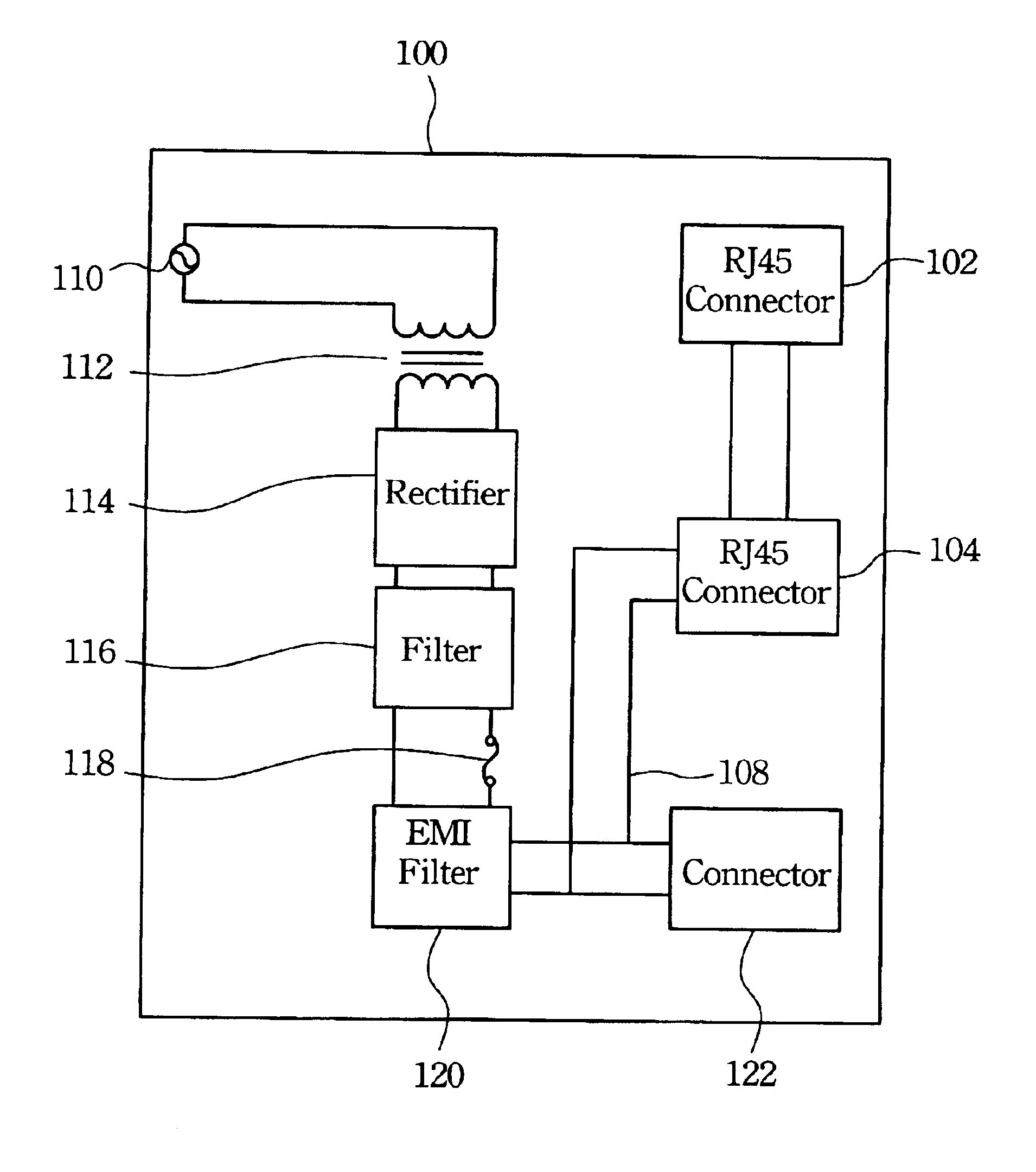
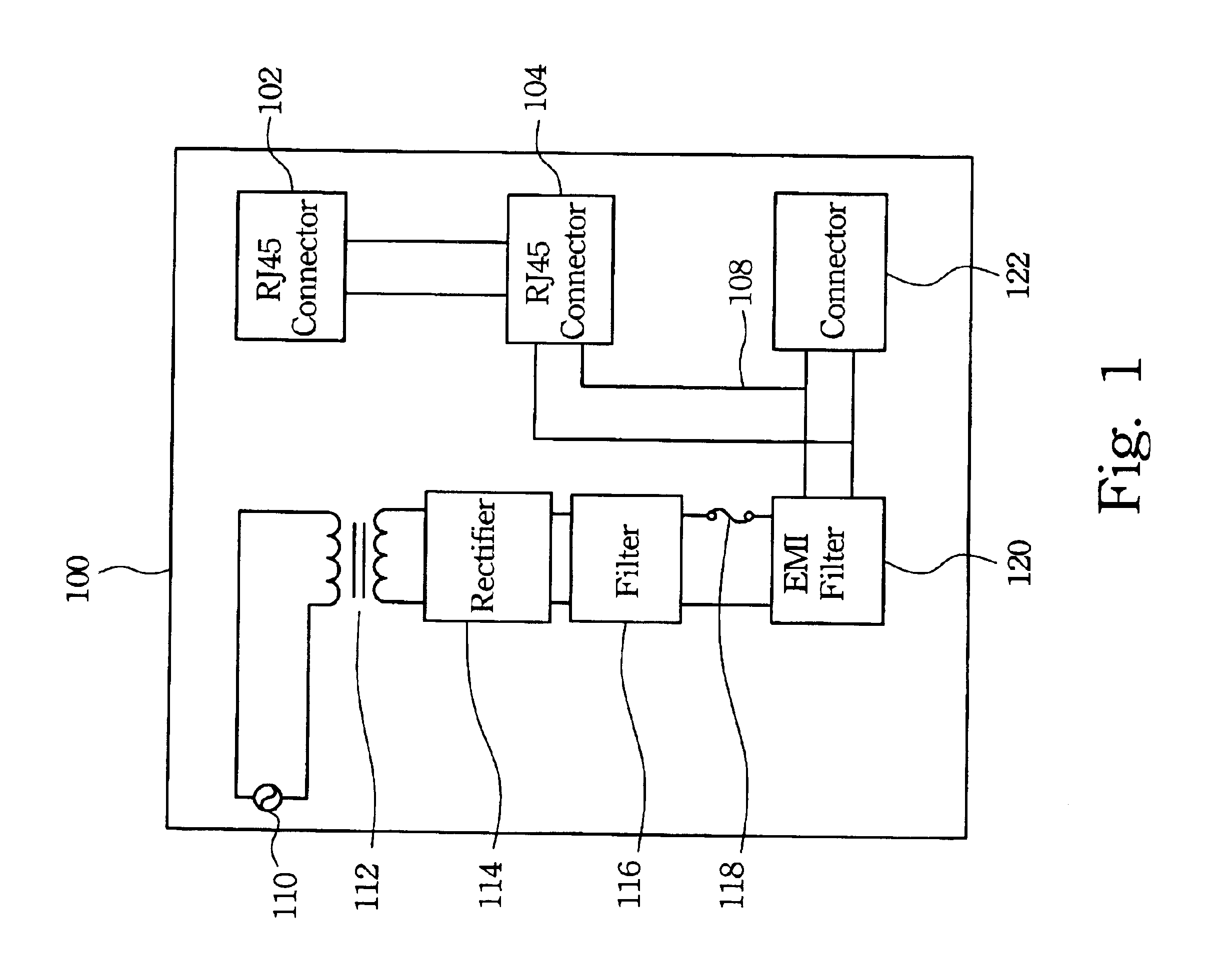
[0015]FIG. 1 illustrates a schematic diagram of a power injector in accordance with the The power injector 100 includes two registered jack-45 (RJ-45) connectors 102 and 104. The two RJ-45 connectors 102 and 104 can be connected together when the RJ-45 connector 102 receives data from the Ethernet. The RJ-45 connector 104 is used to provide the connection point to the terminal. In accordance with the preferred embodiment, the terminal is a Voice over IP (VOIP) device, an Access Point or other Internet device. A conductive line 108 can transmit the power from the AC power source 110 to the RJ-45 connector 104. The RJ-45 connector 104 is coupled with the eight twisted-pair cables to transmit power and data. The different twisted-pair cables are used to respectively transmit power and data.

[0016]Referring to FIG. 1 again, the power injector 100 can also adopt power from the AC power source 110. A transformer 112 and a rectifier 114 are used to transform the AC power into DC power. A f...

second embodiment

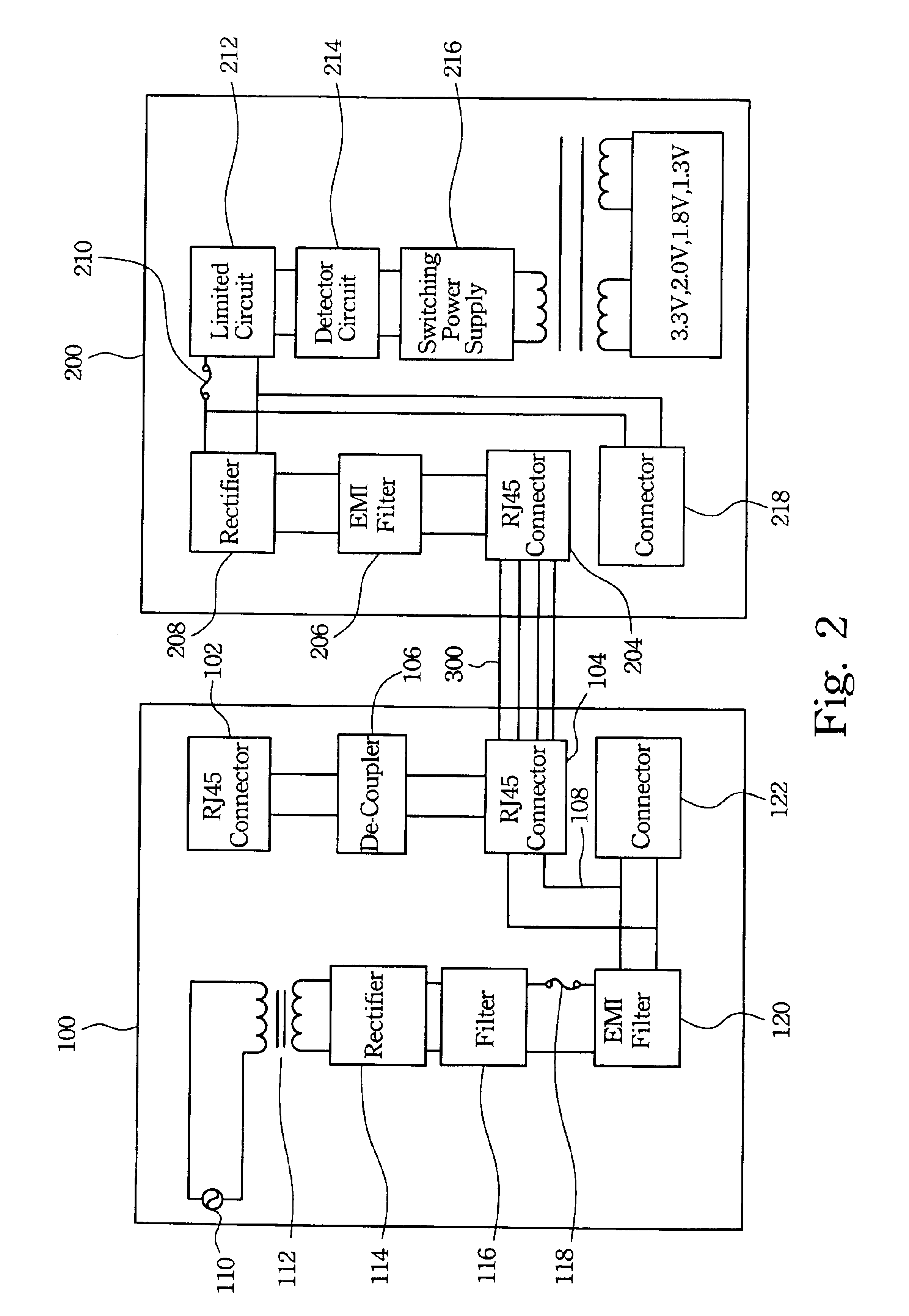
[0020]FIG. 4 illustrates a schematic diagram of a power injector 400 in accordance with the In this embodiment, a coupler 106 is used to couple the RJ-45 connector 102 receiving the data with the RJ-45 connector 104. The power from the AC power source 110 is fed into the coupler 106 through the conductive line 108. Then, this power is fed into the RJ-45 connector 104 through the coupler 106. At this time, power and data are coupled to the same twisted-pair cables for transmitting to the terminal.

[0021]By using the above power injector 400, the terminal can be connected to the RJ-45 connector 104 or the connector 122. On the one hand, the terminal can make a connection with the RJ-45 connector 104 to receive power and data together if the terminal supports POE technology. On the other hand, the terminal can make a connection with the connector 122 to receive power from AC power source 110 if the terminal does not support POE technology. At this time, an additional transmission line ...


PUM

PropertyMeasurementUnit
AC poweraaaaaaaaaa
DC poweraaaaaaaaaa
poweraaaaaaaaaa

Abstract

The present invention provides a power injector apparatus that can supply two power sources, one from the Ethernet and the other from AC power. The Internet device can select the AC power as a power source when the Internet device requires power exceeding the Hub or the Switch can supply. Moreover, the Internet device can select the Ethernet as the power source when the supplied power is sufficient.

Description

FIELD OF THE INVENTION[0001]The present invention relates to a power injector apparatus, and more particularly to a power injector apparatus that can inject power into the transmission line of an Internet system.BACKGROUND OF THE INVENTION[0002]In the past, the Internet apparatus used two independent wires to transmit data and power, respectively. The combination of Rj-45 connectors and four pairs of twisted pair cables is used to transmit data. However, four pins (4, 5, 7, 8 pin) of the RJ-45 connector and two pairs of the twisted pair cables are idle, because only two pairs of the twisted pair cables are occupied while transmitting data. A new technology called Power over Ethernet (POE), therefore, has been developed to utilize the idle pins. This technology uses the unused pins to transmit power. Such technology obviates need for an additional power supply in an Internet apparatus, because required power can be supplied by a central apparatus in an Internet system. This central a...

Claims


Application Information

Patent Timeline
Patent Type & Authority Patents(United States)
IPC IPC(8): H02J1/10G06F1/26
CPCG06F1/263H02J1/10
Inventor HUNG, PAI-FUYOU, REN-HORNGWANG, FENG-HSUEH
Owner ACCTON TECHNOLOGY CORPORATION
Why Eureka
Try Eureka