Optical disk recording method

a technology of optical disk and recording method, which is applied in the field of optical disk recording method, can solve the problems of complex algorithm of forming a record strategy, inability to determine a proper record strategy, and high cost of optical disk recorder hardware, etc., and achieve good record quality and good record quality

Active Publication Date: 2005-06-28
YAMAHA CORP
View PDF3 Cites 71 Cited by
  • Summary
  • Abstract
  • Description
  • Claims
  • Application Information

AI Technical Summary

Benefits of technology

[0010]An object of this invention is to provide an optical disk recording method facilitating to set a waveform adjustment amount capable of obtaining a good record quality, even when data is written in an optical disk for which the waveform adjustment amount of a record signal is not prepared, even when data is written in an optical disk which cannot obtain a good record quality by using a prepared waveform adjustment amount, or even when data is written at a constant angular velocity (CAV).
[0013]For the optical disk without a prepared waveform adjustment amount, the waveform is adjusted by selecting the waveform adjustment amount providing a relatively high signal quality from the prepared waveform adjustment amounts. As compared to forming the waveform adjustment amount, i.e., record strategy from scratch, it is easier to set the waveform adjustment amount. In this case, the test recording and judging the signal quality are performed: first by using typical waveform adjustment amounts for respective record material series (e.g., dye series); next by using prepared waveform adjustment amounts prepared for the disk types belonging to the record material series providing a relatively high signal quality as judged from the results of the first test recording; selecting the waveform adjustment amount providing a relatively high signal quality as judged from the results of the second test recording; adjusting the record signal by the selected waveform adjustment amount; and recording the adjusted record signal in the optical disk. Since all the prepared waveform adjustment amounts are not necessary to be used for the test recording, the time taken to select the waveform adjustment amount can be shortened. An area of the optical disk used by the test recording can be made small. The record power providing a good signal quality at the selected waveform adjustment amount is selected in accordance with the second test recording, and the adjusted record signal is recorded at this record power.
[0020]Judging the signal quality of the reproduced test signals may be performed by measuring an area surrounded by an abscissa and an each curve of the characteristics of a C1 error rate relative to an asymmetry value β sliced at a slice level of a certain C1 error rate value, or by measuring an area surrounded by an abscissa and an each curve of the characteristics of a jitter value relative to an asymmetry value β sliced at a slice level of a certain jitter value, and by judging that the signal quality is relatively higher as the area is larger.

Problems solved by technology

Newly sold disks or unknown maker disks have no record strategy stored in the memory so that the proper record strategy cannot be determined.
In this case, high speed and bulk hardware of high cost is necessary for an optical disk recorder.
In addition, an algorithm of forming a record strategy is complicated and it takes a fairly long time to form the strategy.
Even an optical disk having the record strategy stored in the memory does not provide a high record quality because of manufacture variation or if minor change or the like in the optical disk is made without notice.
It is therefore difficult to set a record strategy capable of obtaining a good reproduced signal quality at each record velocity.

Method used


Image

  • Optical disk recording method
  • Optical disk recording method
  • Optical disk recording method

Examples


Embodiment Construction

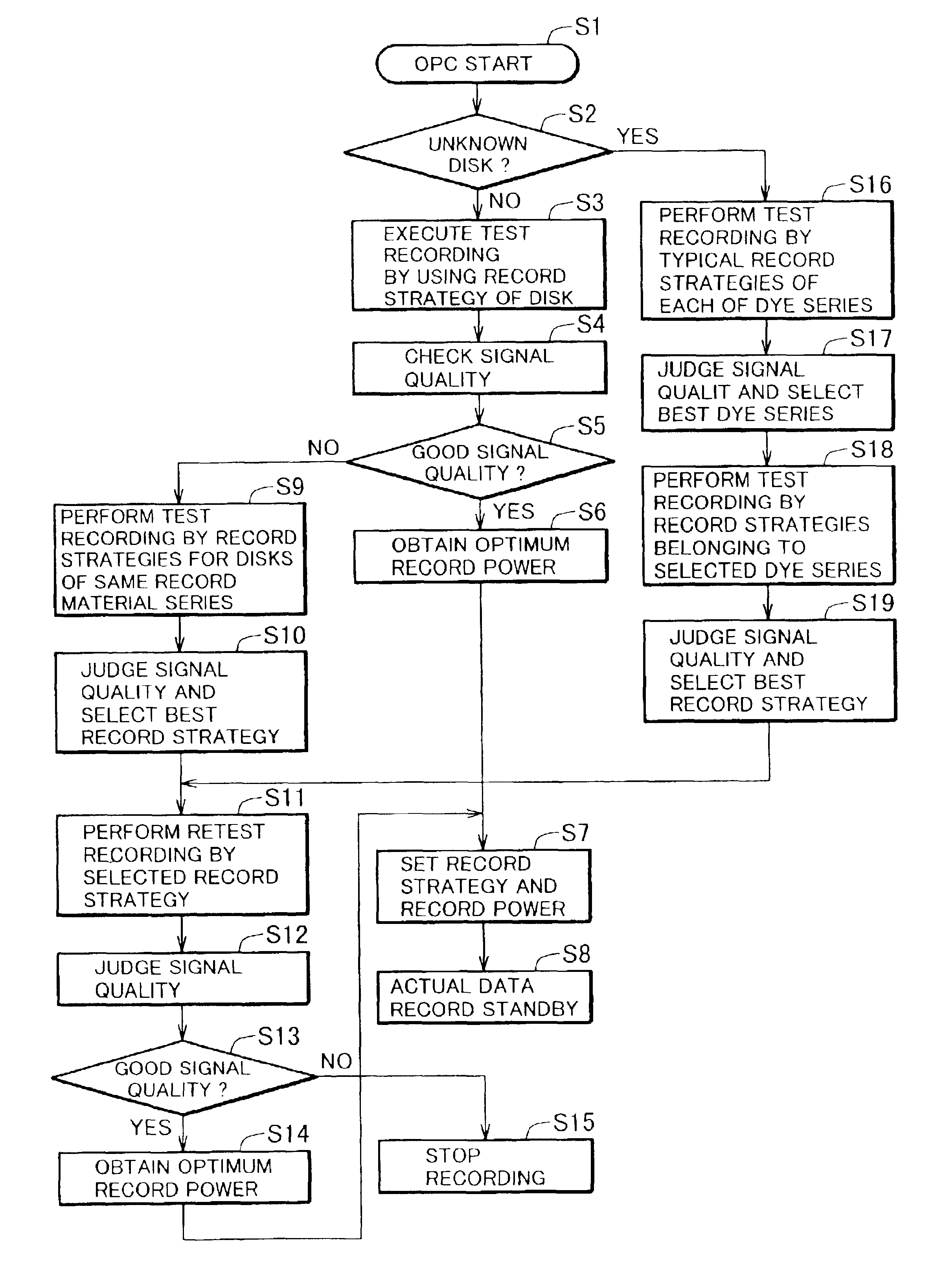
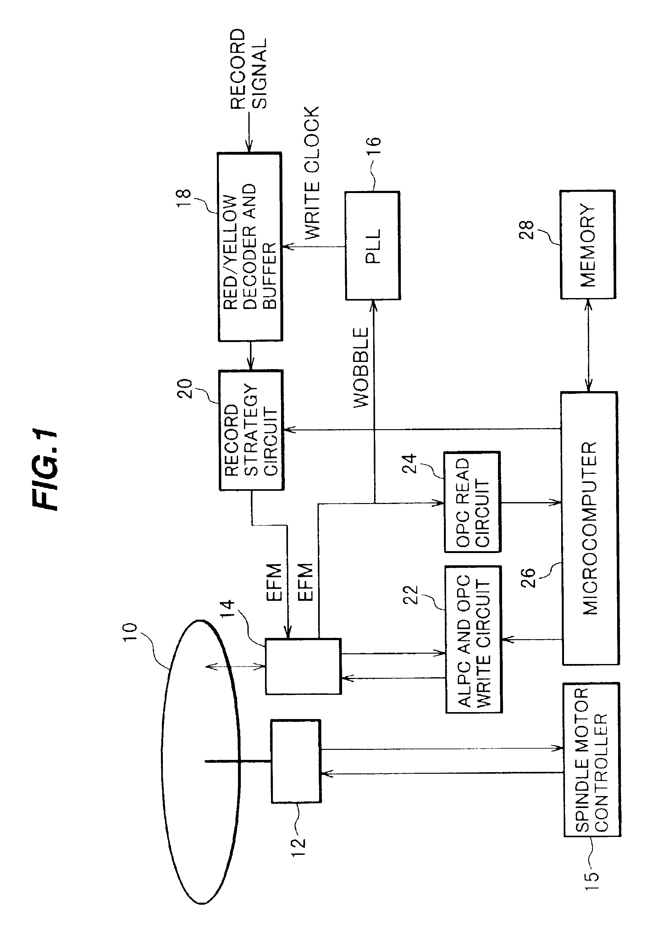
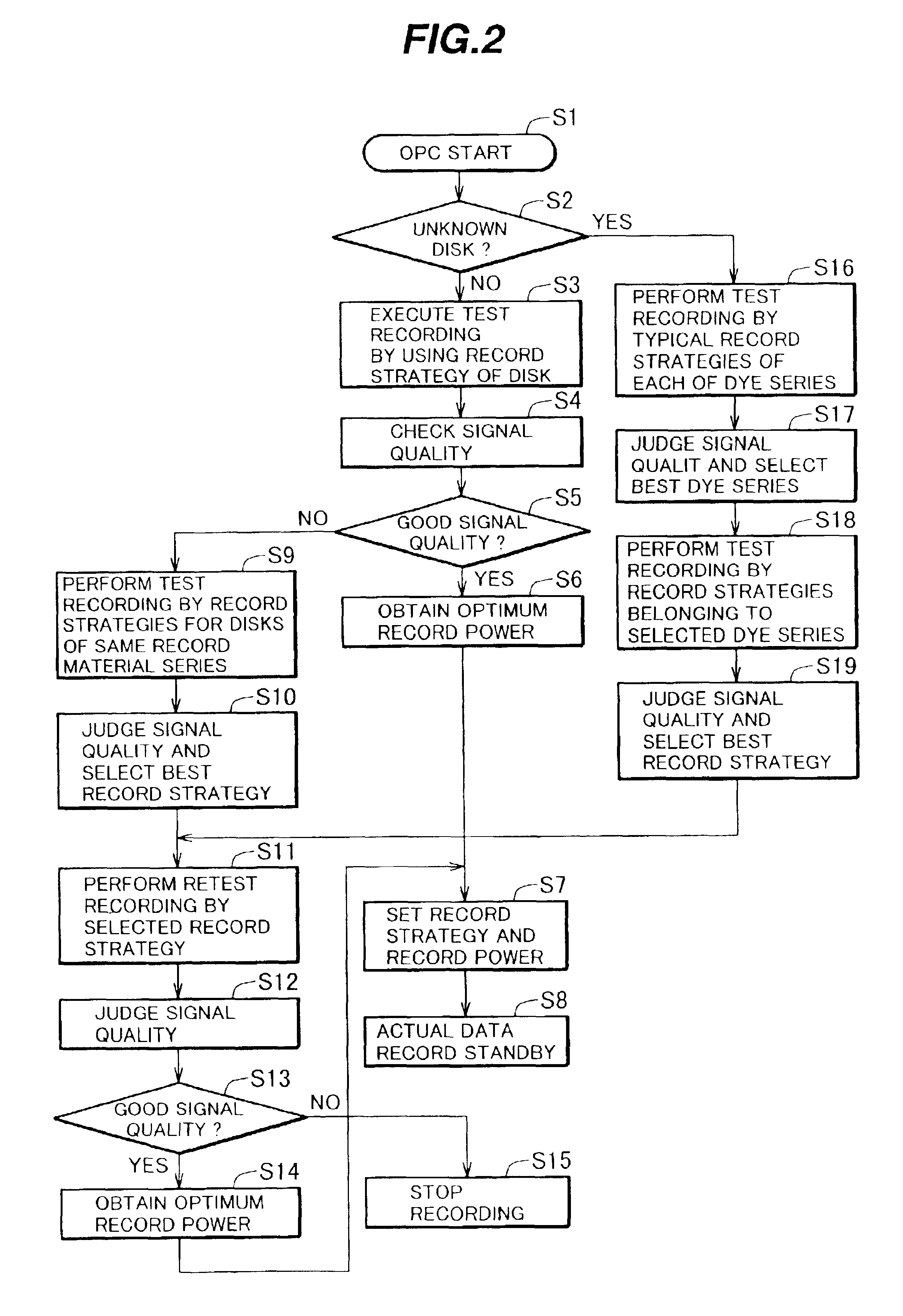
[0032]FIG. 1 is a diagram showing the outline structure of a CD-R / RW drive (an optical disk recording / reproducing apparatus capable of recording / reproducing a CD-R disk and a CD-RW disk) to which the optical disk recording method of the invention is applied.

[0033]In this optical disk recording / reproducing apparatus, data (record strategy) of a waveform adjustment amount to be added to a record signal in accordance with the signal length (pit length, land length) for each of a plurality of disk types is prepared and stored in a memory, the waveform adjustment amount corresponding to a disk type is selected, and the record signal is adjusted by the selected waveform adjustment amount to write actual data in an optical disk. An optical disk 10 (CD-R disk or CD-RW disk) is driven by a spindle motor 13, and an optical pickup 14 reads / writes data from / into the optical disk. A spindle motor controller 15 controls the spindle motor 12 to perform constant linear velocity (CLV) control or CAV...


PUM

PropertyMeasurementUnit
frequencyaaaaaaaaaa
lengthaaaaaaaaaa
record velocitiesaaaaaaaaaa

Abstract

For an optical disk for which a record strategy is not prepared in a memory and an optical disk which cannot obtain a good signal quality by using the record strategy prepared in the memory, test recording is performed by using all record strategies prepared in the memory or properly adopted record strategies by changing the record power. A record strategy providing a relatively high signal quality is selected to record data in the optical disk. The record strategies for such optical disks can be easily set.

Description

CROSS REFERENCE TO RELATED APPLICATION[0001]This application is based on Japanese Patent Application No. 2001-248645, filed on Aug. 20, 2001, the entire contents of which are incorporated herein by reference.BACKGROUND OF THE INVENTION[0002]A) Field of the Invention[0003]The present invention relates to an optical disk recording method of recording data in an optical disk by preparing, for each of a plurality of disk types, data of a waveform adjustment amount to be added to a record signal in accordance with the length of the record signal. Even when data is written in an optical disk for which the waveform adjustment amount of a record signal is not prepared, even when data is written in an optical disk which cannot obtain a good record quality by using a prepared waveform adjustment amount, or even when data is written at a constant angular velocity (CAV), the waveform adjustment amount capable of obtaining a good record quality can be easily set.[0004]B) Description of the Relat...

Claims


Application Information

Patent Timeline
Patent Type & Authority Patents(United States)
IPC IPC(8): G11B7/0045G11B7/00G11B7/125G11B7/1267
CPCG11B7/1267
Inventor MORISHIMA, MORITO
Owner YAMAHA CORP
Why Eureka
Try Eureka