Adaptive playout buffer and method for improved data communication

a playout buffer and buffer technology, applied in the field of data communication, can solve the problems of excessive overrun or underrun, clear undesirable for users, and overall end-to-end delay of the data stream being transmitted in the playout buffer, so as to reduce the average filling level of the playout buffer, reduce the impact of quality of connection, and reduce the average waiting time in the pob

Inactive Publication Date: 2005-06-28
CISCO TECH INC
View PDF16 Cites 23 Cited by
  • Summary
  • Abstract
  • Description
  • Claims
  • Application Information

AI Technical Summary

Benefits of technology

[0021]Suitably, the apparatus can be arranged to reduce the average filling level of the playout buffer at the end of the time period by removing data, preferably a predefined number of bytes, from the playout buffer. Existing slip mechanisms for handling overruns can thereby be employed.
[0022]With this arrangement, the average waiting time in the POB is reduced and gradual drifts in the POB filling level due to clock speed differences are automatically corrected. In addition, the data loss caused by the slips is distributed over time thereby reducing the impact on the quality of the connection.
[0023]The playout buffer can have a fixed size for each data connection, the fixed size being established when the connection is set up. This enables rapid variations in the jitter in the network to be accommodated without excessive overruns or underruns.

Problems solved by technology

The use of a playout buffer inevitably introduces an overall end-to-end delay in the data stream being transmitted.
This is clearly undesirable for users and may require the use of echo cancellation techniques or the like.
This can lead to a drift in the average filling level of the playout buffer which, if not corrected, can lead to excessive overruns or underruns.
However, it is not suitable for a synchronous situation where the service clock frequency is constant.
The problem with the above described conventional POB management techniques is that the methods used to estimate the maximum jitter are somewhat imprecise.
In consequence, the resulting estimate of the maximum jitter is generally extremely pessimistic.
Furthermore, the jitter experienced on any particular connection within the network can change rapidly over time due to changing network conditions, such as other connections being set up and removed.

Method used


Image

  • Adaptive playout buffer and method for improved data communication
  • Adaptive playout buffer and method for improved data communication
  • Adaptive playout buffer and method for improved data communication

Examples


Embodiment Construction

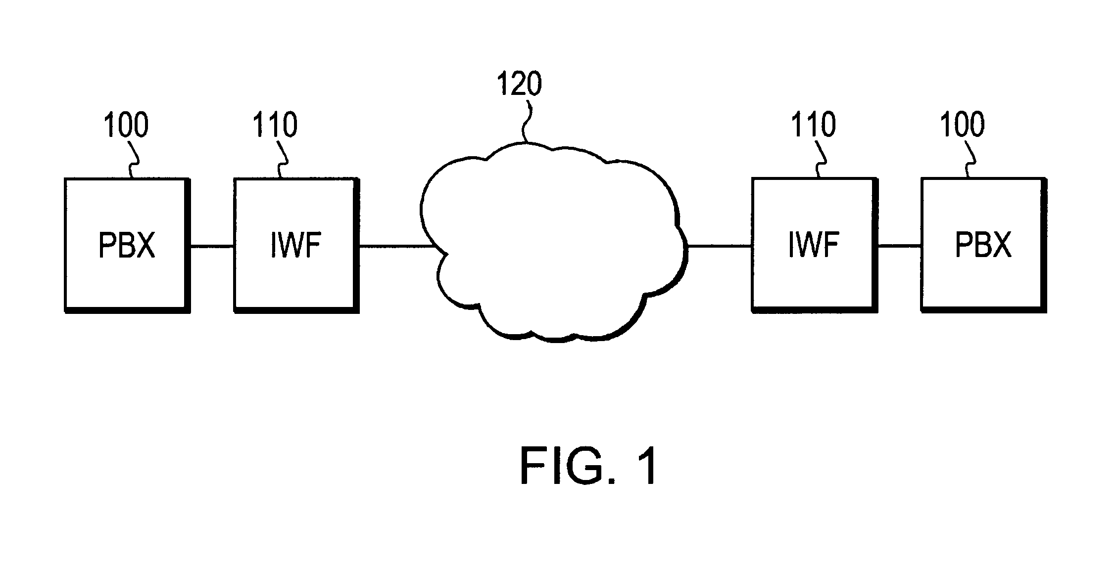
[0029]FIG. 1 is a schematic diagram showing a data communications system in which two Private Branch Exchanges (PBX) 100 are interconnected via a CBR connection within an ATM data communications network 120. PBXs 100 are connected to the network at edge nodes 110. Edge nodes 110 provide an interworking function (IWF) to convert the Constant Bit Rate (CBR) traffic from the PBX into ATM cells for transmission over network 120.

[0030]While this embodiment has been developed for use in ATM networks, it will be appreciated that the techniques to be described would be equally applicable to other types of packet-based networks, such as those based on Frame Relay or the Internet Protocol (IP).

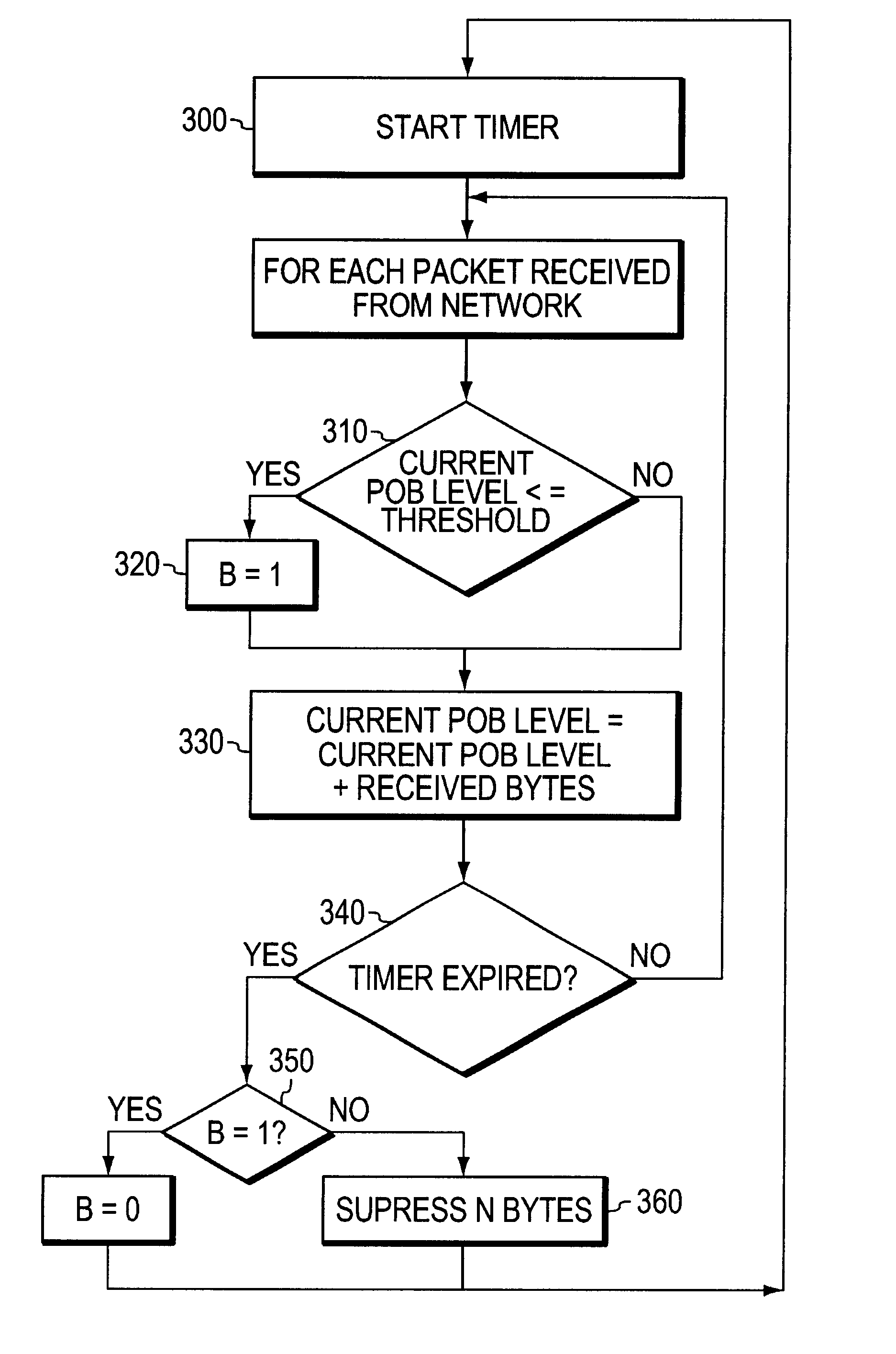
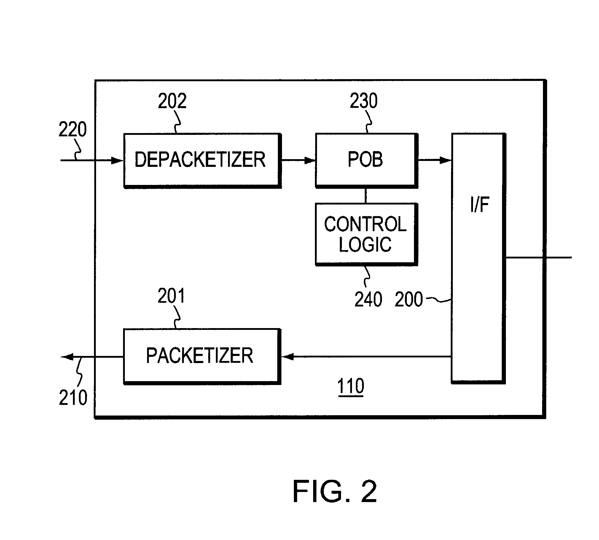
[0031]As shown in FIG. 2, edge nodes 110 comprise an interface 200 for interfacing with the PBX nodes 100, Playout Buffer (POB) 230 and associated control logic 240. Node 110 includes packetizer 201 which places data to be transmitted from PBX 1000 into data packets which are then sent over ATM network ...


PUM


Abstract

An adaptive apparatus and method for managing a playout buffer (POB) in an edge node of a packet-based data communications network, such as an ATM network, in order to reduce the end-to-end communication delay introduced thereby and to allow the POB filling level to be corrected in the event of clock speed differences. A monitoring mechanism determines if the minimum filling level of the playout buffer over a time period whereby the average filling level of the playout buffer is reduced according to the minimum filling level of the playout buffer over the time period.

Description

BACKGROUND OF THE INVENTION[0001]1. Field of the Invention[0002]The invention relates to data communications and, more particularly, to improvements in the management of playout buffers (POB) in packet-based communications networks.[0003]2. Description of Prior Art[0004]In order to transport constant bit rate (CBR) traffic, such as telephone conversations or real time video transmissions, modern high-speed, packet-based telecommunications networks, such as those based on Asynchronous Transfer Mode (ATM) technology, make use of playout buffers in receiving nodes at the edge of the network to smooth out differences in the queuing delays that each packet in a data stream experiences as it passes through the network.[0005]The playout buffer is generally arranged to operate as a first-in / first-out (FIFO) buffer in which data is placed when it arrives at the node. Data is then dequeued from the playout buffer uniformly so as to preserve the constant bit rate of the data stream being trans...

Claims


Application Information

Patent Timeline
Patent Type & Authority Patents(United States)
IPC IPC(8): H04L12/28H04L12/56H04L29/06
CPCH04L49/90
Inventor DUAULT, MAURICEPUCCI, BERNARDLEROY, SERGERICHTER, GERARDKERMAREC, FRANCOISFICHOU, ALINE
Owner CISCO TECH INC
Why Eureka
Try Eureka