Use of cabin air for generation of water via exhaust gas of a fuel cell

Active Publication Date: 2008-07-31
AIRBUS OPERATIONS GMBH
View PDF6 Cites 2 Cited by
  • Summary
  • Abstract
  • Description
  • Claims
  • Application Information

AI Technical Summary

Benefits of technology

[0028]According to an embodiment of the water generation system, an aircraft with a water generation system as described above is provided. Therefore, water may be generated on board the aircraft without a plurality of cooling cir

Problems solved by technology

However, this arrangement may be complex and

Method used


Image

  • Use of cabin air for generation of water via exhaust gas of a fuel cell
  • Use of cabin air for generation of water via exhaust gas of a fuel cell
  • Use of cabin air for generation of water via exhaust gas of a fuel cell

Examples


Embodiment Construction

[0038]The examples described and drawings rendered are illustrative and are not to be read as limiting the scope of the invention as it is defined by the appended claims.

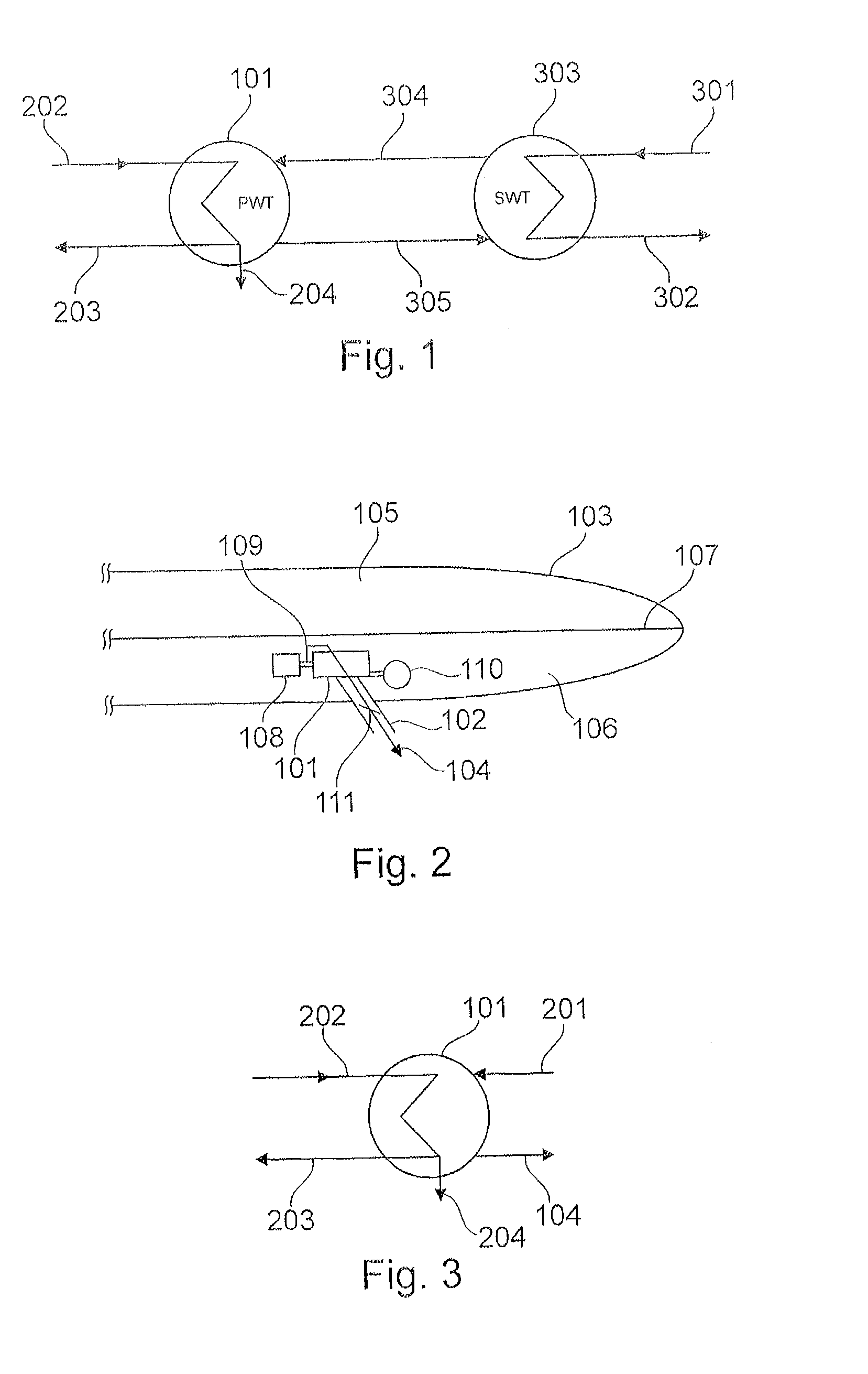
[0039]FIG. 1 shows a concept for indirect cooling by means of coolant. Hereby, a primary heat exchanger 101 is provided through which the fuel cell exhaust gas passes. The fuel cell exhaust gas enters the primary heat exchanger 101 through line 202 and leaves it through the outlet line 203.

[0040]Also provided is a secondary heat exchanger 303 comprising an inlet line for external air 301 and an outlet line for external air 302. At cruising altitude, the external air may have an effective temperature of approximately −20° C. or lower.

[0041]Provided between the primary heat exchangers 101 and the secondary heat exchangers 303 is a coolant circuit 304, 305 in order to ensure a heat connection between the two heat exchangers 101, 303 and on the other hand to prevent the icing of the primary heat exchanger 101. The cooli...


PUM


Abstract

A water generation system for the generation of water on board an aircraft, in one example, may be used for the cooling of the fuel cell exhaust air cabin air which is drawn off through the condenser due to the pressure difference between the cabin pressure and ambient pressure and may not require extensive cooling circuits or pumps.

Description

REFERENCE TO RELATED APPLICATIONS[0001]This application claims the benefit of the filing date of German Patent Application No. 10 2006 034 814.1 filed Jul. 27, 2006 and of U.S. Provisional Patent Application No. 60 / 820,493 filed Jul. 27, 2006, the disclosure of which applications is hereby incorporated herein by reference.FIELD OF THE INVENTION[0002]The field relates to the generation of water on board aircraft. In particular, the field relates to a water generation system for the generation of water on board an aircraft, a condenser for condensing water from an exhaust gas from a fuel cell device on board an aircraft, the use of a water generation system of this kind, an aircraft and a method for the generation of water on board an aircraft.BACKGROUND OF THE INVENTION[0003]In aircraft, fuel cell arrangements can be used for the recovery of water from the fuel cell exhaust gas. Hereby, it is necessary to condense out the water contained in the exhaust gas flow water vapor by means o...

Claims


Application Information

Patent Timeline
IPC IPC(8): F25B39/04F28F1/10
CPCB01D5/0045Y02T90/36B64D2041/005B64D11/04Y02T90/40
Inventor WOLFF, CHRISTIANMAIBACH, MARKUSHOFFJANN, CLAUS
Owner AIRBUS OPERATIONS GMBH
Why Eureka
Try Eureka