Method and apparatus for high-speed synchronous digital acquisition derived in real -time from analog samples

a digital acquisition and real-time technology, applied in the field of digital data acquisition instruments, can solve the problems of limiting the resolution of edge detection to a resolution, the approach of synchronous logic analysis is limited, and the oversampled logic analyzer cannot detect more than one clock edge and store more than one related data. achieve the effect of high ra

Inactive Publication Date: 2005-06-28
TEKTRONIX INC
View PDF11 Cites 14 Cited by
  • Summary
  • Abstract
  • Description
  • Claims
  • Application Information

AI Technical Summary

Benefits of technology

[0007]These and other deficiencies of the prior art are addressed by the present invention of a method and apparatus for real-time derivation of precise digital clock edges and synchronous logic samples from multi-bit analog samples. Specifically, according to methods and apparatus of the present invention, a digital input signal is sampled at a very high rate with an analog sample-and-hold array. These analog samples are then analyzed in real-time by an array of signal processing elements referred to as real-time Nyquist engine (RTNE) slices that produce digital information which gets processed further by digital logic to derive the precise time of all clock edges cros

Problems solved by technology

Unfortunately, practical ratios of oversampling limit the resolution of edge detection to a resolution that is too coarse to support the small setup and hold windows required by synchronous buses whose clock rate is significantly faster than the logic clock of the oversampled logic analyzer.
Moreover, the described oversampled logic analyzer cannot detect more than one clock edge and store more than one related data sample per channel for each logic clock.
Unfortunately, this approach is limited as a synchronous logic analyzer because: (1) the memory depths that can be practically implemented with analog sampling are several ord

Method used


Image

  • Method and apparatus for high-speed synchronous digital acquisition derived in real -time from analog samples
  • Method and apparatus for high-speed synchronous digital acquisition derived in real -time from analog samples
  • Method and apparatus for high-speed synchronous digital acquisition derived in real -time from analog samples

Examples


Embodiment Construction

[0016]The subject invention will be primarily described within the context of a logic analyzer (LA). However, it will be appreciated by those skilled in the art that the invention may be advantageously employed in any single-channel or multiple-channel signal measurement or analysis device, such as a digital storage oscilloscope (DSO) in which one or more digital input signals are periodically sampled to ascertain changes in logic level over time.

[0017]The invention provides apparatus and method for sampling digital data at an extremely high effective sample rate. The subject invention acquires multiple samples during each sample clock period to identify one or more changes in logic state, as well as temporal offsets associated with each change. In this manner, multiple edges may be detected during each sample clock period.

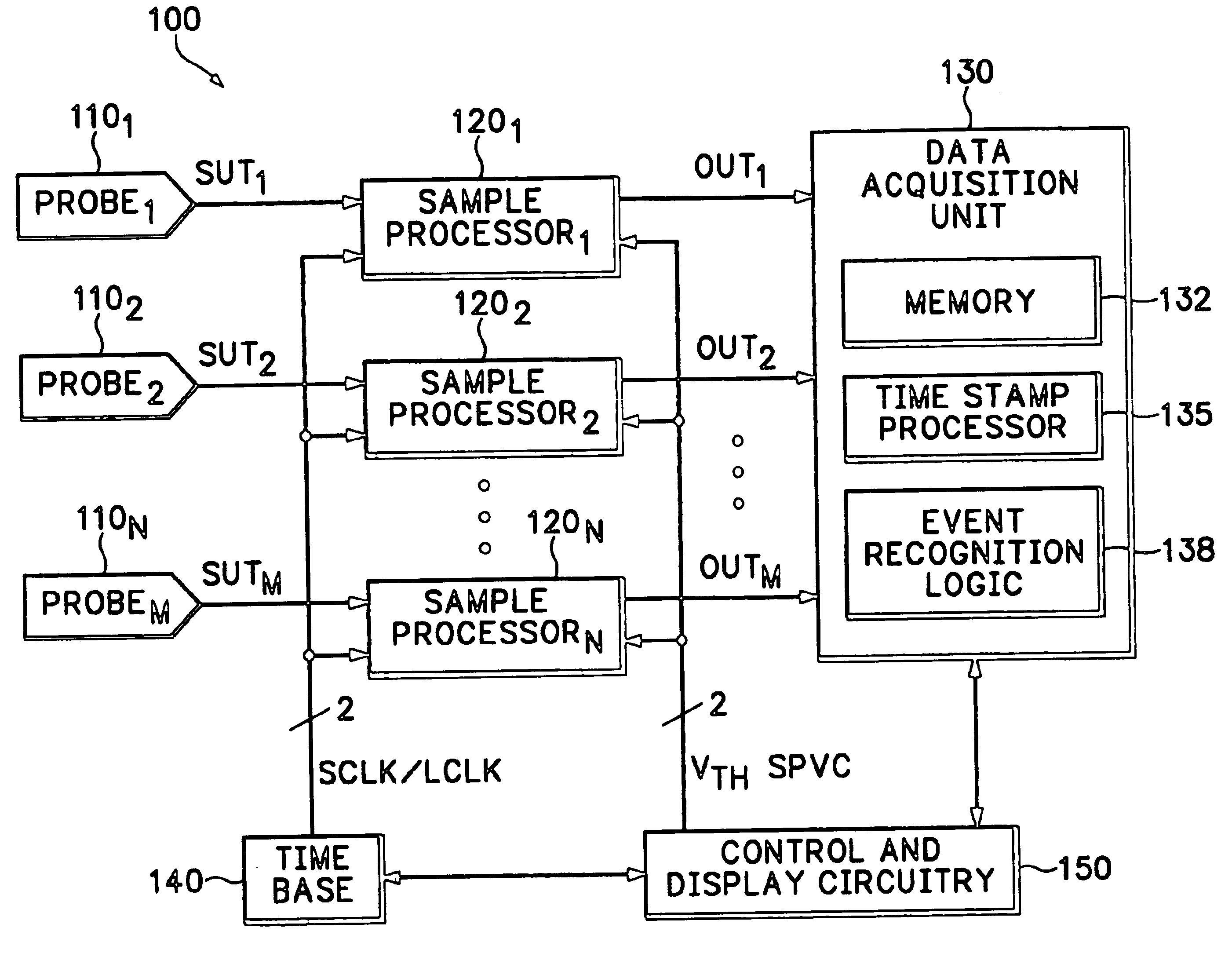
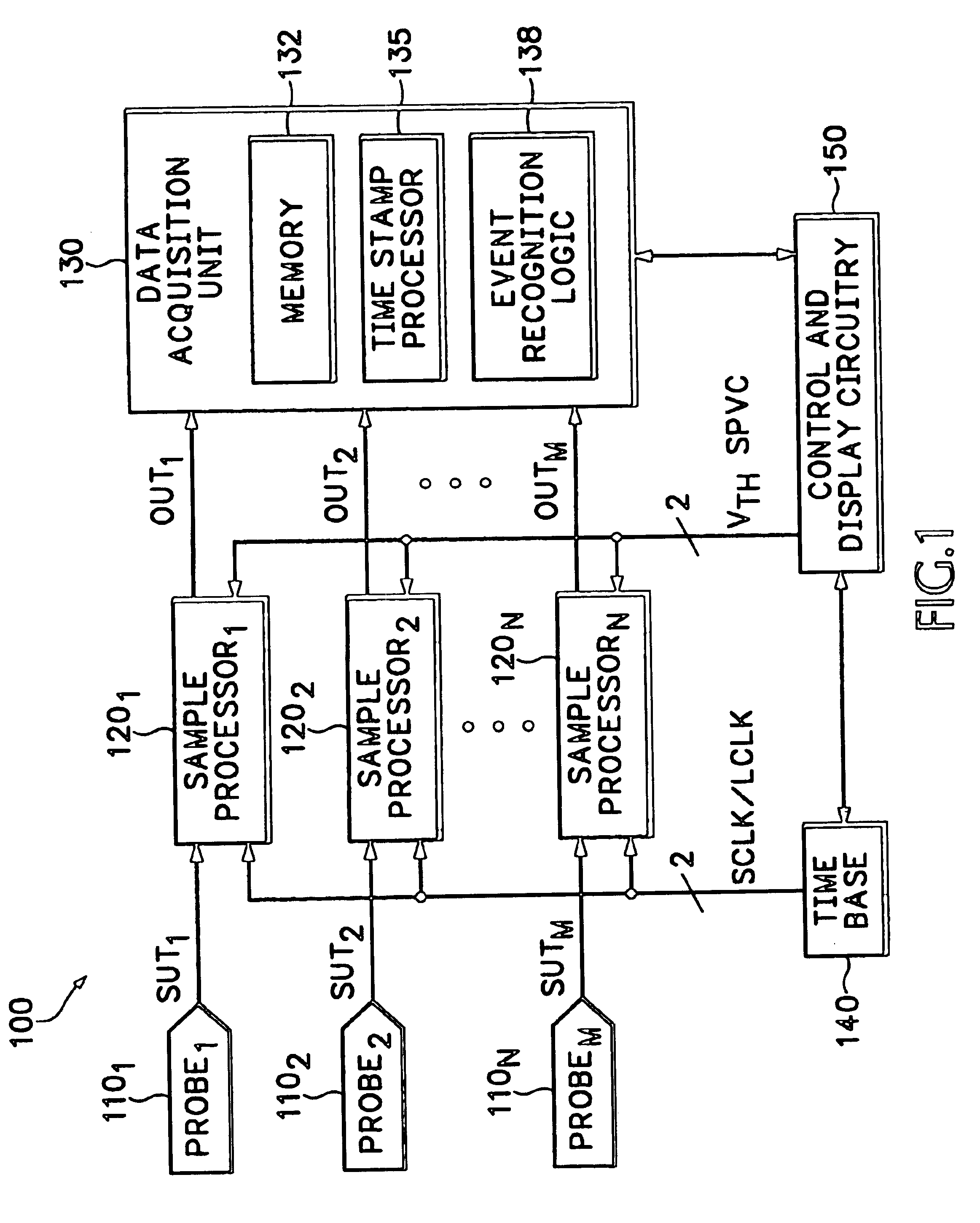
[0018]FIG. 1 depicts a high level block diagram of a logic analyzer according to an embodiment of the present invention. Specifically, each of a plurality of prob...


PUM


Abstract

A method and apparatus for real-time derivation of precise digital clock edges and synchronous logic samples from a digital signal having a clock channel and at least one data channel acquires a plurality of temporally offset analog samples during each of a sequence of sample periods and from consecutive samples where there is a logic level transition estimates an edge time. From the edge times for the clock channel an offset is added and applied to the at least one data channel to determine the synchronous logic samples for the data channel at each offset clock edge time.

Description

FIELD OF THE INVENTION[0001]The invention relates generally to digital data acquisition instruments such as logic analyzers and, more particularly, methods and apparatus supporting very high speed acquisition of logic level data.BACKGROUND OF THE INVENTION[0002]Logic analyzers are digital data acquisition instruments that allow a user to acquire and analyze digital data from a large number of logic signals, such as all of the address, data and control signals associated with a microprocessor. Each logic signal is compared to a logic threshold or thresholds and results in one of two logic states; namely, high or low, one or zero, true or false. The behavior of groups of these signals can then be monitored to analyze the behavior of the circuitry or instrument under test.[0003]U.S. Pat. No 5,526,286, issued Jun. 11, 1996, to Sauerwein et al. for “Oversampled Logic Analyzer” discloses a digital oversampling system and is incorporated herein by reference in its entirety. In the disclose...

Claims


Application Information

Patent Timeline
IPC IPC(8): G06F19/00G06F11/25
CPCG06F11/25
Inventor RICHMOND, GARY K.
Owner TEKTRONIX INC
Why Eureka
Try Eureka