
Structurally integrated solar collector

a solar collector and structure technology, applied in the direction of hybrid energy generation, pv power plants, lighting and heating apparatus, etc., can solve the problems of substantial reduction of daylight illumination, loss of heat sources, and add to heat gain, so as to minimize the required cooling load, minimize the direct solar heating of the enclosed structure, and minimize the effect of roof shading

Inactive Publication Date: 2005-07-05
SAWTOOTH SOLAR ROOFING LTD
View PDF31 Cites 20 Cited by
  • Summary
  • Abstract
  • Description
  • Claims
  • Application Information

AI Technical Summary

Benefits of technology

[0025]It is an object of the present invention to minimize roof shading by indirect day lighting and to obviate daytime artificial lighting requirements.
[0026]It is another object of the present invention to minimize the direct solar heating of the enclosed structure.
[0027]It is a further object of the present invention to capture sunlight generated heat for diversion away from the enclosed structure during the summer, in order to minimize required cooling load and for use within the structure during winter in order to minimized the heating load.
[0029]It is still another object of the present invention to minimize electrical demand and reduce electrical lighting and mechanical space conditioning to ‘stand-by-status.’

Problems solved by technology

While a roof seals a building from the environment, it also results in substantially reduced daylight illumination, the loss of a heat source in cool seasons and the collection of heat in warm seasons.
Skylights may or not be fitted to improve illumination but may add to the heat gain in the warmer months.
Technologies that collect some aspect of solar energy introduce some negative side effects that require energy consumption to offset.
Solar heat exchangers for water and space heating or for electrical energy collection cause a build up of heat in summer months.
At additional expense and effort, solar photovoltaic panels may be laid horizontally or framed to sit at an angle.
While photovoltaic panels permit the production of electricity, the per-kilowatt cost of generation is high.
Additionally, the panels block solar illumination of the structure thereby trading off one form of solar energy for another.
While these inventions are useful for producing heat or photovoltaic energy, they do not represent an integral construction member that has the capability of not only collecting heat for use in heating inside air but also producing electrical energy from the heat air collected.

Method used


Image

  • Structurally integrated solar collector
  • Structurally integrated solar collector
  • Structurally integrated solar collector

Examples


Embodiment Construction

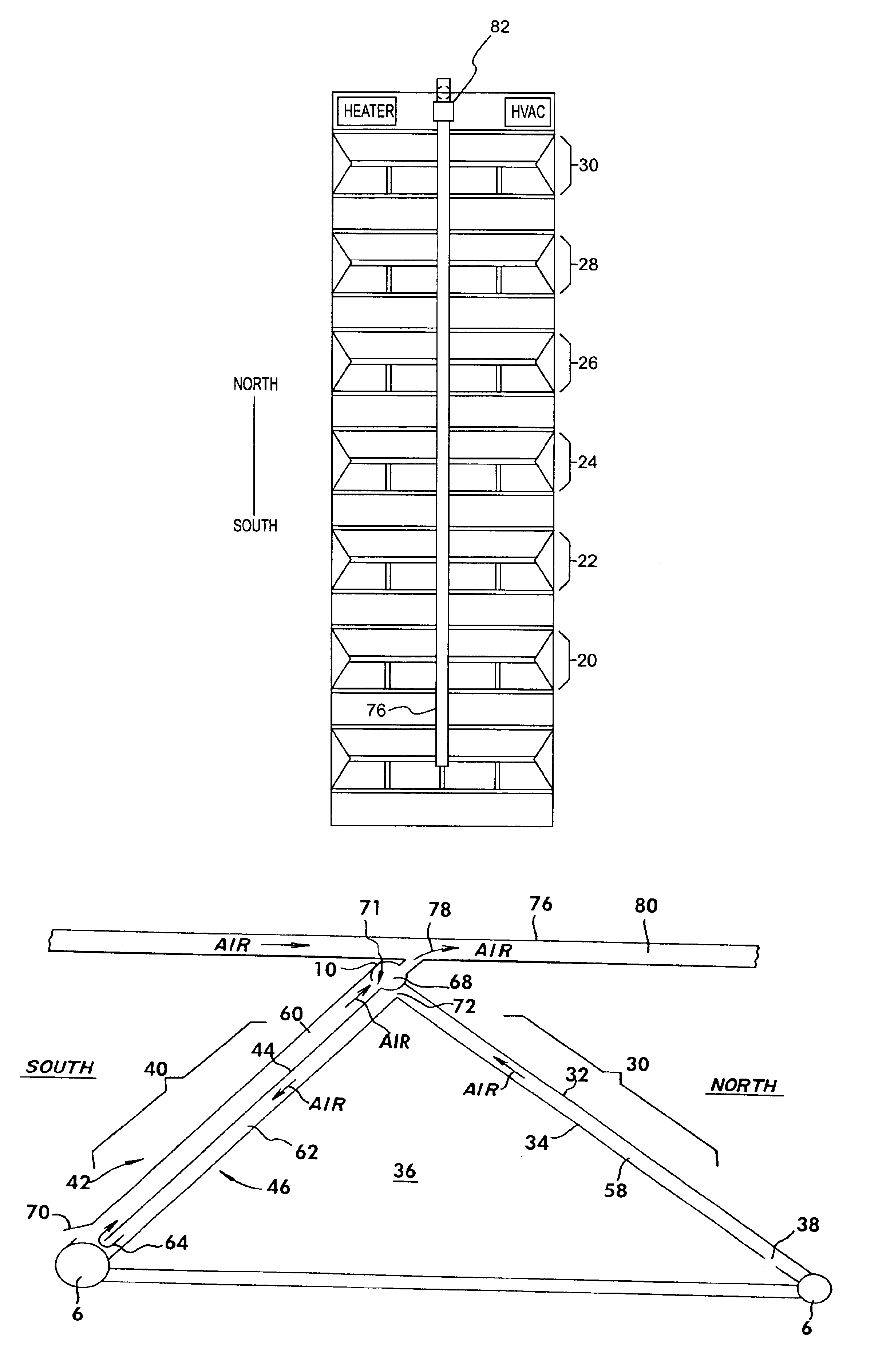
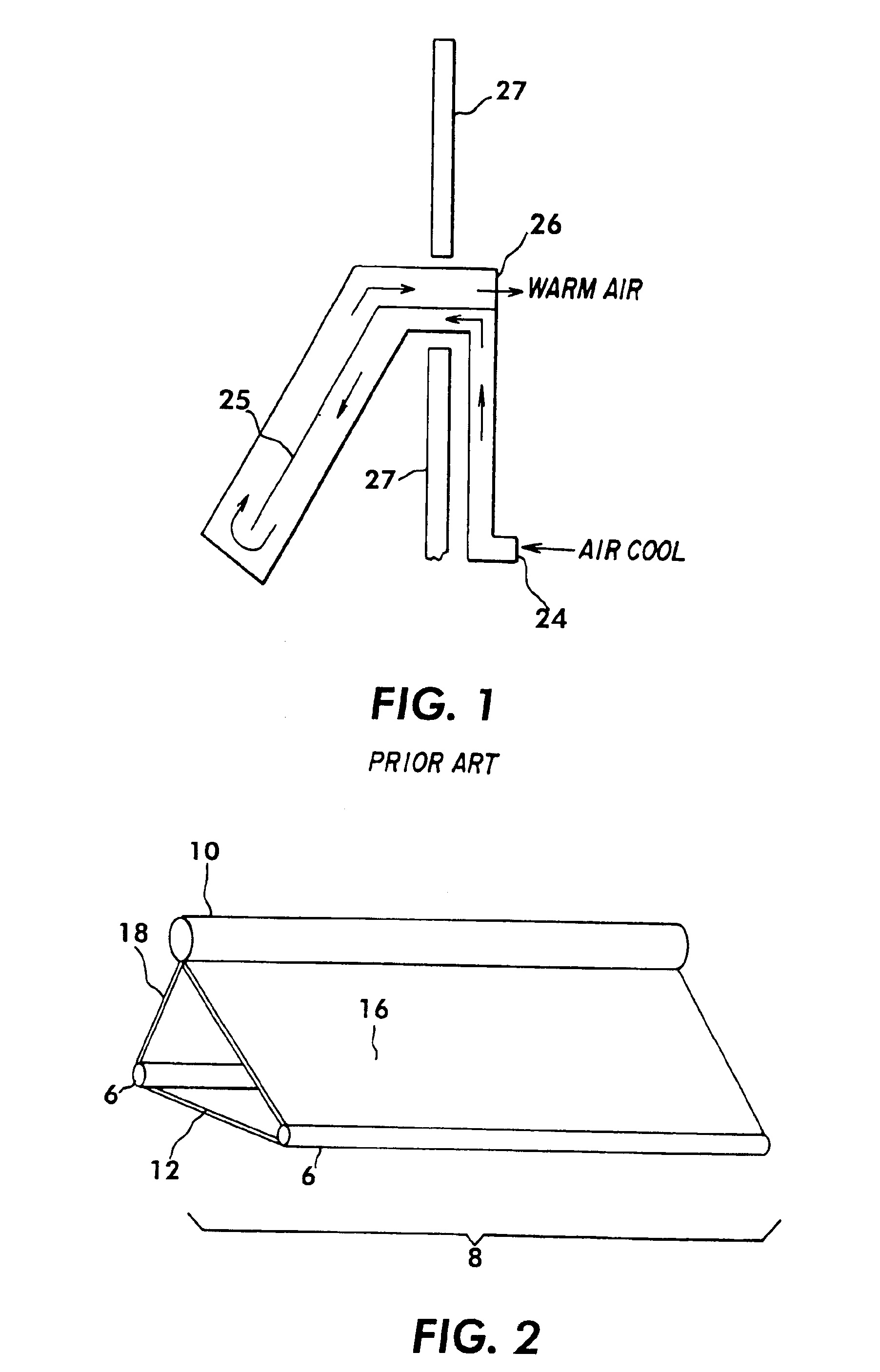
[0045]An embodiment of the present invention is a roof structure that integrates solar collectors into the structure of the roof itself. Referring to FIG. 2 a cross section of an integrated truss collector 8 is illustrated. The integrated truss collector 8 illustrated comprises two lower rails 6, a cross member 12, a truss air duct 10, solar energy collection panel 16 and daylighter panel 18. In an embodiment of the present invention, the solar energy collection panel 16 is oriented in a southerly direction and the daylighter panels 18 are oriented in a northerly direction. Each end of the integrated truss collector 8 is supported by a weight-bearing structure.

[0046]As illustrated In FIG. 2, the integrated truss collector 8 comprises a single panel length, however this is not meant as a limitation. As would be apparent to those skilled in the art of the present invention, the number of panels may be determined by the producer of the integrated truss collector 8, subject to limitatio...


PUM


Abstract

A structurally integrated solar collector. Roof and wall covering components are integrated with solar collectors to permit solar energy to be converted to heat, electricity and hot water for use within a building. A roof truss is described that additionally captures sunlight for illuminating a building. The roof and wall components are adaptable to heating and cooling seasons so as to minimize the loss of air-conditioned air in the summer time and to maximize solar heating during cold months. Solar energy captured by a structurally integrated solar collector can be directly converted to electricity through use of photovoltaic materials or by harnessing airflow through structurally integrated solar collector to obtain electricity through mechanical conversion.

Description

CROSS REFERENCE TO RELATED APPLICATIONS[0001]This application claims priority under 35 U.S.C. §119(e) from provisional application No. 60 / 326,297 filed Oct. 1, 2001. The No. 60 / 326,297 provisional application is incorporated by reference herein, in its entirety, for all purposes.FIELD OF THE INVENTION[0002]The present invention relates to building construction and the placement of solar energy collectors thereon. More specifically, the present invention relates to integrating solar collectors with building components so as to permit the simultaneous solar harvesting of heat and light, the conversion thereof to electrical energy, and the selective use of heat for heating and cooling.BACKGROUND OF THE INVENTION[0003]Traditional roof technologies construct elevated covers to buildings. A roof typically comprises a layer of impermeable tar, tarpaper or concrete laid over a wood or metal platform (deck) of corrugated metal sheeting. While a roof seals a building from the environment, it ...

Claims


Application Information

Patent Timeline
IPC IPC(8): F24J2/04E04D13/18H01L31/048H01L31/058H02S20/23H02S40/44
CPCF24J2/0444F24J2/045F24J2/0483H02S40/44H02S20/23Y02B10/12Y02B10/70Y02E10/44Y02E10/60Y02B10/20F24S10/25F24S20/66F24S20/67Y02A30/60Y02B10/10Y02E10/50
Inventor O'LEARY, PATRICK
Owner SAWTOOTH SOLAR ROOFING LTD
Learn More