Coated crossfire tube assembly

a crossfire tube and crossfire technology, applied in the ignition of turbine/propulsion engines, engine starters, lighting and heating apparatus, etc., can solve problems such as premature replacement, and achieve the effect of increasing coating hardness and resistance to wear and oxidation

Inactive Publication Date: 2005-07-05
ANSALDO ENERGIA SWITZERLAND AG
View PDF9 Cites 20 Cited by
  • Summary
  • Abstract
  • Description
  • Claims
  • Application Information

AI Technical Summary

Benefits of technology

The present invention provides a crossfire tube assembly that is more resistant to wear and oxidation. Additionally, a coating process is provided that does not require machining after coating and results in increased coating hardness.

Problems solved by technology

The technical problem addressed in this patent is the wear and tear that occurs on crossfire tubes in industrial gas turbine engines, which can lead to premature replacement and increased operating costs. The crossfire tubes are used to transfer flames between combustors during the initial start-up period and are subject to frictional rub contact with crossfire receptacles and wear from engine vibrations. The patent aims to extend the life of crossfire tubes to reduce operating costs associated with premature replacement.

Method used


Image

  • Coated crossfire tube assembly
  • Coated crossfire tube assembly
  • Coated crossfire tube assembly

Examples


Embodiment Construction

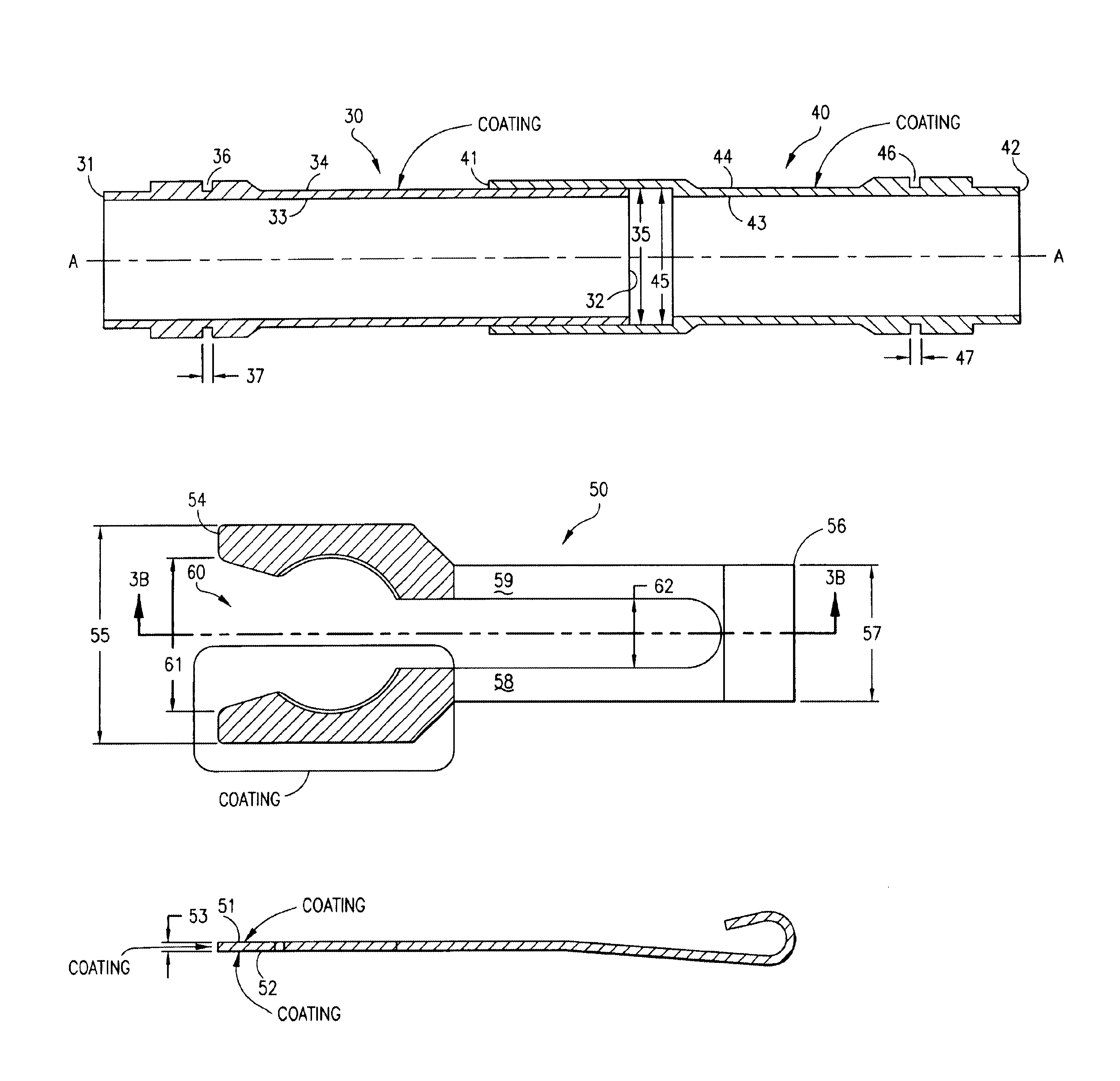
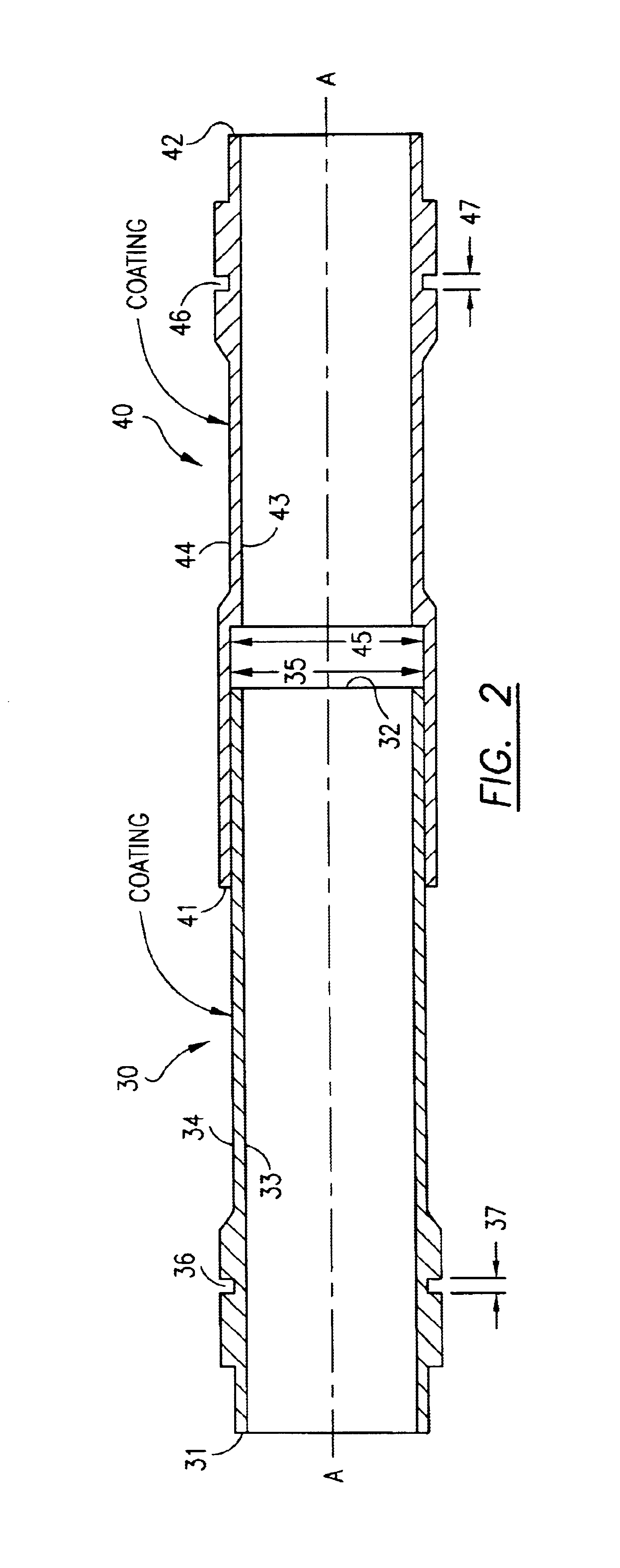
[0016]The preferred embodiment of the present invention, a crossfire tube assembly for connecting adjacent combustors in a gas turbine engine, is shown in detail in FIGS. 2-4. Referring now to FIG. 2, a hollow inner tube 30 is shown having a first axis A-A, a first inner end 31, a second inner end 32, a first inner wall 33, and a first outer wall 34 coaxial with and radially outward of first inner wall 33. First outer wall 34 also has a first diameter 35 proximate second inner end 32 and a first groove 36 having a first groove width 37 which is circumferentially disposed about first outer wall 34 proximate first inner end 31. The crossfire tube assembly also contains a hollow outer tube 40 that is coaxial with hollow inner tube 30 and has a first outer end 41, a second outer end 42, a second inner wall 43, and a second outer wall 44 that is coaxial with and radially outward from second inner wall 43. Second inner wall 43 has a second diameter 45 proximate said first outer end, which...


PUM


Abstract

A crossfire tube assembly is provided having an increased resistance to wear and oxidation. This increased resistance is provided by the application of coatings to the mating surfaces between the crossfire tube and crossfire tube clip. In the preferred embodiment, a physical vapor deposition (PVD) Titanium Aluminum Nitride coating is applied to the outer walls of the crossfire tubes which is used in combination with an air plasma spray (APS) Aluminum Bronze coating applied to the crossfire tube clip open end that mates with the crossfire tubes. The coating combination serves to protect the components from frictional wear and extend their life. In an alternate embodiment, the crossfire tubes also contain a plurality of air purge holes that provide a layer of cooling air along the crossfire tube inner wall.

Description


Claims


Application Information

Patent Timeline
Owner ANSALDO ENERGIA SWITZERLAND AG
Why Eureka
Try Eureka