Personal table

a table and personal technology, applied in the field of tables, can solve the problems of awkward or difficult to move the table, and the conventional table tops constructed from wood or metal are also relatively expensive, and achieve the effects of simple manufacturing, increased legroom for the user, and increased strength and rigidity of the table top

Inactive Publication Date: 2005-07-05
LIFETIME PRODUCTS
View PDF39 Cites 34 Cited by
  • Summary
  • Abstract
  • Description
  • Claims
  • Application Information

AI Technical Summary

Benefits of technology

[0013]One aspect of the present invention is a relatively small-sized table that is designed for use by a single person. This type of table that is intended for use by an individual is referred to as a personal table, but it will be appreciated that more than one person could use the table if desired. Advantageously, the personal table is relatively small and light-weight, which makes the table easy to move and transport. Significantly, because the table is sized and configured for personal use, it does not take up unnecessary space or provide a large amount of unused space. Therefore, the personal table provides ample space for a single user without requiring a large area or wasting unnecessary space.
[0025]Additionally, the personal table is easy to assemble, which reduces manufacturing and labor costs. Further, the consumer can easily assemble the personal table and the consumer will appreciate many of the aspects of the personal table such as the light-weight, easy height adjustment, portability, sturdiness, and wide variety of uses in any different environments.

Problems solved by technology

Table tops constructed from wood, particle board or metal, however, are often relatively heavy and this may make the table awkward or difficult to move.
Conventional table tops constructed from wood or metal are also relatively expensive and the table tops must generally be treated or finished before use.
In addition, these relatively heavy table tops increase the cost of transportation, shipping, and storage of the tables.
Disadvantageously, these light-weight table tops frequently require reinforcing members or other structural parts such as frames, railings, brackets and the like to strengthen the table top.
These additional parts may increase the strength of the table top, but these additional parts also increase the weight of the table.
In addition, these additional parts increase manufacturing costs and require additional time to assemble the table.
Furthermore, these additional parts may have sharp edges that can injure the user's legs, arms or other body parts.
Disadvantageously, because the telescoping assemblies include overlapping components, the assembly is relatively heavy.
Additionally, conventional tables may use other mechanisms to allow the height of the table to be adjusted, but these devices are often relatively complex and require additional parts, which increases the costs to manufacture and assemble the table.
These complex designs may also result in tables that are relatively difficult to use.
The connecting rods, however, increase the cost of the table, reduce space under the table top, and may easily break or become disconnected.
Disadvantageously, the detachable legs often create a table that is not sturdy or stable.
Additionally, moving a table with this type of attachment when the legs are still attached is often difficult because the legs may undesirably detach.
These mechanical attachments, such as plastic or metal clips or brackets, often break or are otherwise damaged.
Further, attachment of these devices to the table top may structurally weaken the table top, which may allow the table to unexpectedly fail.
Further, attaching the four separate attachment mechanisms to the table top by fasteners such as screws or bolts may undesirably weaken the table top.
The four separate legs, however, increase the weight of the table.
In additional, the four legs require four separate attachment mechanisms to attach the legs to the table top, which increases the cost and complexity of the table.

Method used


Image

  • Personal table
  • Personal table
  • Personal table

Examples


Embodiment Construction

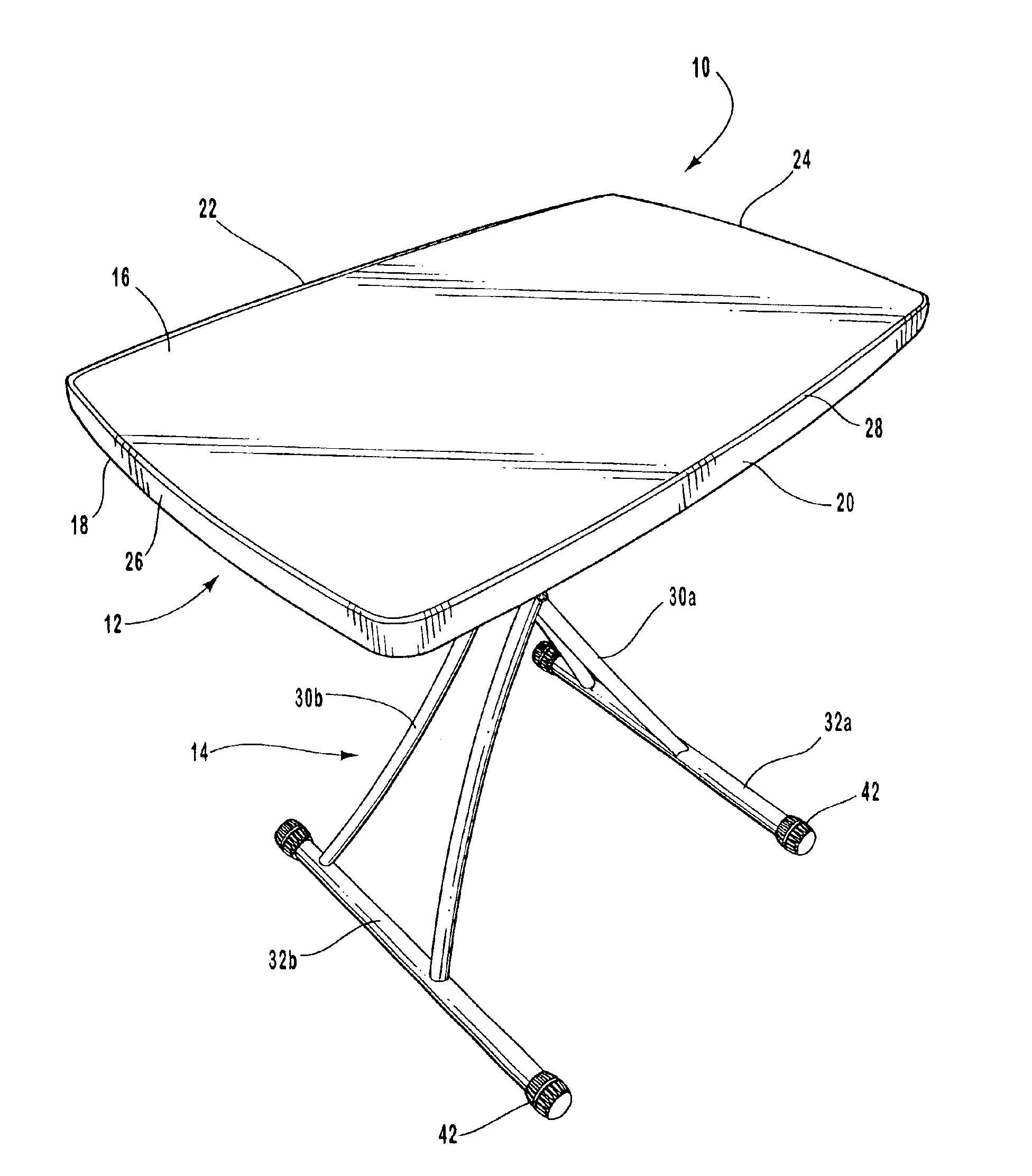
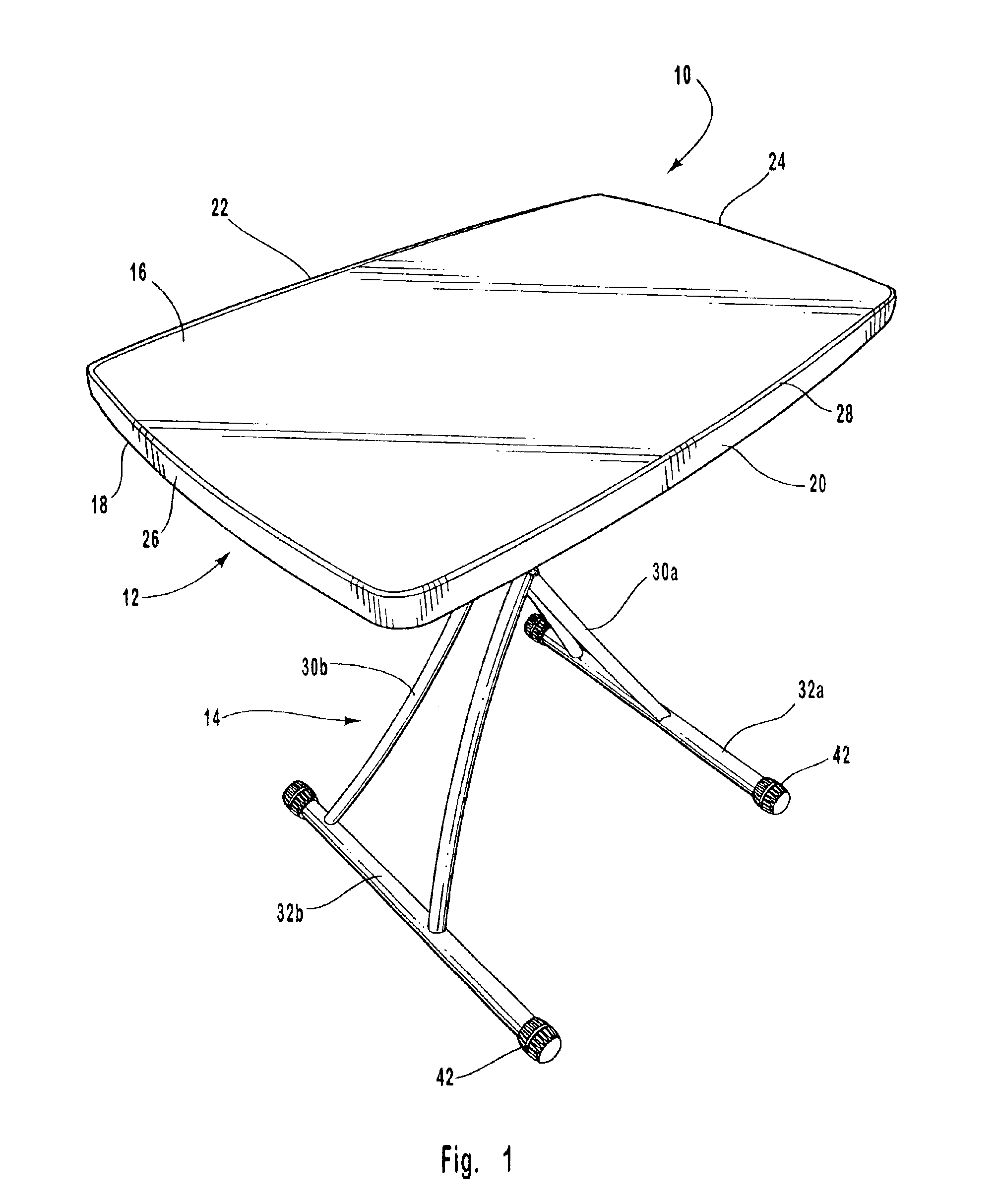
[0056]The present invention is directed towards a table and, in particular, to a table that is intended to be used by a single user at one time. The principles of the present invention, however, are not limited to a table intended for use by an individual user. It will be understood that, in light of the present disclosure, the table can be used by more than one user at any given time.

[0057]Additionally, to assist in the description of the table, words such as top, bottom, front, rear, right and left are used to describe the accompanying figures. It will be appreciated, however, that the table can be located in a variety of desired positions—including various angles, sideways and even upside down. A detailed description of the table now follows.

[0058]As seen in FIG. 1, an exemplary table 10 is shown. The table 10 is preferably a relatively small-sized table that is intended for use by a single person at one time. Advantageously, because the table 10 is sized and configured for perso...


PUM


Abstract

A personal table is provided having a table top supported by a support assembly. The table top is preferably constructed from blow-molded plastic and the support assembly preferably includes a first leg and a second leg that are pivotally connected. The legs desirably have a generally X-shaped configuration when the legs are placed in an upright position and the legs can be collapsed into a storage position. Each of the legs may include a lower portion, a body portion and an upper portion that is preferably selectively connected to the table top. The legs, for example, can be connected to the table top by inserting the upper portions of the legs into leg receiving recess formed in the table top. The leg receiving recesses are preferably integrally formed in the bottom surface of the table top as part of a one-piece construction. Desirably, a plurality of leg receiving recesses are formed in the bottom surface of the table top and the legs can be selectively attached to the leg receiving recesses in order to vary the height of the table.

Description

CROSS-REFERENCE TO RELATED APPLICATIONS[0001]This application claims priority to and the benefit of U.S. provisional patent application Ser. No. 60 / 347,556, filed Jan. 9, 2002, entitled PERSONAL TABLE; U.S. provisional patent application Ser. No. 60 / 364,712, filed Mar. 14, 2002, entitled PERSONAL TABLE; and U.S. provisional patent application Ser. No. 60 / 421,221, filed Oct. 25, 2002, entitled PERSONAL TABLE. In addition, this application is a continuation-in-part of U.S. design patent application Ser. No. 29 / 167,624, filed Sep. 18, 2002, entitled TABLE LEG, now U.S. Pat. No. D469,994; this application is a continuation-in-part of U.S. design patent application Ser. No. 29 / 167,628, filed Sep. 18, 2002, entitled TABLE TOP, now U.S. Pat. No. D469,996; and this application is a continuation-in-part of U.S. design patent application Ser. No. 29 / 167,611, filed Sep. 18, 2002, entitled TABLE TOP, now U.S. Pat. No. D470,352. Each of these patents and applications are expressly incorporated h...

Claims


Application Information

Patent Timeline
Patent Type & Authority Patents(United States)
IPC IPC(8): A47B3/08A47B13/08A47B3/00A47B3/06A47B3/02A47B9/00A47B9/16
CPCA47B3/02A47B9/16
Inventor WINTER, DAVID C.JONES, JAYNYE, STEPHEN F.SMITH, BRANDONASHBY, KENTSTRONG, L. CURTIS
Owner LIFETIME PRODUCTS
Why Eureka
Try Eureka